


– 5 –
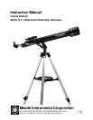
INTRODUCTION
Before you begin, we urge you to take a few minutes to completely read this manual so that you can
get the best use of the equipment. This manual details the set-up, operation, specifications and
optional accessories of the Polaris 60-AZ-D altazimuth refracting telescope. Designed for both
astronomical and terrestrial observing, the Polaris 60-AZ-D will be your companion in exploring a
universe of celestial and earthly objects.
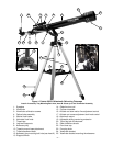
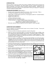
STANDARD EQUIPMENT (Refer to Fig. 1)
• Complete optical tube assembly (objective lens diameter = 60mm; focal length = 700mm)
• Full-length, fully adjustable, aluminum tripod and accessory tray.
• H 25mm (28X), H 12.5mm (56X), and SR 4mm (175X) Eyepieces (0.965" O.D. “Outside Diameter”)
• 3x Barlow Lens (0.965" O.D.)
• Diagonal mirror (0.965" O.D.)
• 5 x 24mm viewfinder with bracket
• Altazimuth mount with micro-altitude control
• Hardware package: A. 3 bolts (3" long) with wing nuts and washers
B. 3 screws (1/2" long) with wing nuts and screwdriver tool
Note: All other necessary hardware provided in place.
• StarLocator astronomy software (separate instructions supplied in software package)
UNPACKING AND ASSEMBLY
First time assembly of the telescope should require a set up of about 15 minutes. To set up the
telescope, follow this procedure:
1. Remove and identify the telescope’s components, using the listing above.
2. Attach the 3 aluminum tripod legs (7, Fig. 1) to the base of the altazimuth mount (10, Fig. 1) with
the 3 hinged leg brace supports (8, Fig. 1) facing inward. Three bolts (11, Fig. 1), each about 2"
long, with washers and wing nuts, are provided for this purpose in hardware package “A.” Stand
the telescope upright, spreading the tripod legs evenly apart so that the accessory tray can be
positioned to attach to the 3 leg braces.
3. Attach the accessory tray (9, Fig. 1) to the leg brace supports (8, Fig. 1) by threading the bolt on
the bottom of the tray into the center hole located where the three brace supports meet (see Fig.
1, Inset A) and turning the tray clockwise. Tighten to a firm feel, but do not overtighten—you will
need to remove the tray if you wish to collapse the tripod. To remove the tray, just rotate the tray
counterclockwise untill the tray comes loose.
4. Extend the sliding center portion of the adjustable height tripod leg (19, Fig. 1) to the desired length
for all 3 legs. Lock the tripod legs by tightening the leg lock thumbscrew (20, Fig. 1) to a firm feel.
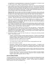
5. Remove the two vertical lock knobs (D, Fig. 2) from the optical
tube assembly.
6. Place the optical tube between the forks of the azimuth mount (A,
Fig. 2), oriented as shown in Fig. 2.
7. Slide the altitude rod (B, Fig. 2) into the hole in the altitude coarse
adjustment control assembly (C, Fig. 2). Tighten to a firm feel.
8. Thread a vertical lock knob (D, Fig. 2) through each of the holes in
the forks of the azimuth mount (A, Fig. 2) and tighten to a firm feel.
9. Attach the viewfinder bracket (2, Fig. 1) to the telescope using the
2 thumbscrews provided (25, Fig. 1). The thumbscrews fit through
the 2 holes located at the base of the viewfinder bracket and
thread into the main tube (see Fig. 1, Inset B).
Fig. 2 Mounting the optical
tube assembly: (A) azimuth
mount; (B) altitude rod;
(C) altitude coarse adjustment
control; (D) vertical lock knob.
B A
C
D