


– 5 –
INTRODUCTION
Before you begin, we urge you to take a few minutes to completely read this manual so that you can
get the best use of the equipment.This manual details the set-up, operation, specifications and optional
accessories of the Telestar 60-AZ-A altazimuth refracting telescope. Designed for both astronomical
and terrestrial observing, the Telestar 60-AZ-A will be your companion in exploring a universe of
celestial and ear
thly objects.
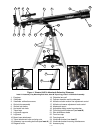
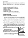
STANDARD EQUIPMENT (Refer to Fig. 1)
• Complete optical tube assembly (objective lens diameter = 60mm; focal length = 700mm)
• Full-length, fully adjustable, aluminum tripod and accessory tray.
• MA25mm (28X), MH9mm eyepieces (1.25" O.D. “Outside Diameter”)
• 2x Barlow Lens (1.25" O.D.)
• Diagonal mirror (1.25" O.D.)
• 5 x 24mm viewfinder with bracket
• Altazimuth mount with micro-altitude control
• Hardware package: A. 3 bolts (2" long) with wing nuts and washers
B. 3 screws (1/2" long) with nuts
Note: All other necessary hardware provided in place.
UNPACKING AND ASSEMBLY
You will need a Phillips-head screwdriver to assemble the tripod.
1. Remove and identify the telescope’s components, using the listing above.
2. Attach the 3 aluminum tripod legs (
7, Fig. 1) to the base of the altazimuth mount (10, Fig. 1) with
the 3 leg brace supports (8, Fig. 1) facing inward. Line up the holes of the tripod legs (11, Fig. 1)
with the holes on the mount base attachment and thread the three included bolts through the holes.
Thread the wing nuts over the bolts and hand-tighten to a firm feel. Stand the telescope upright
and spread the tripod legs evenly apart so that the accessory tray can be positioned for attachment
to the leg braces.
3. To attach the leg braces to the tripod, line up the holes in the leg braces (
9, Fig. 1) with the holes
in the leg brace supports (8, Fig. 1) and slide the the included 1/2” screws through the holes.
Thread the included nuts over the end of the bolts and hand-tighten to a firm feel.
4. To attach the accessory tray (26, Fig. 1) to the leg braces (9, Fig. 1), place the round accessory
tray over the over mounting bolt hole (12, Fig. 1). Thread the attachment knob into the mounting
hole on top of the tr
a
y and tur
ning the knob clockwise. Tighten to a firm feel, but do not
overtighten—you need to remove the tray if you wish to collapse the tripod. To remove the tray, just
rotate the knob countercloc
kwise and remo
ve the knob. You can then lift and remove the tray.
5. Extend the sliding center portion of the adjustable height tripod leg (
19, Fig. 1) to the desired length
for all 3 legs. Lock the tripod legs by tightening the leg lock thumbscrew (
20, Fig. 1) to a firm feel.
See Inset B.
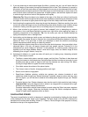
6. Remove the two vertical lock knobs (D, Fig. 2) from the optical tube
assemb
ly
.
7.
Place the optical tube betw
een the forks of the azimuth mount (
A,
Fig.
2
), or
iented as sho
wn in
Fig.
2
.
8. Slide the altitude rod (B, Fig. 2) into the hole in the altitude coarse
adjustment control assembly (C, Fig. 2). Tighten to a firm feel.
9.
Thread a v
er
tical loc
k knob (
D
,
Fig.
2
) through each of the holes in
the forks of the azimuth mount (A, Fig. 2) and tighten to a firm feel.
10.
Attach the vie
wfinder bracket (
2,
Fig.
1
) to the telescope using the
2 thumbscrews provided (25, Fig. 1). The thumbscrews fit through
the 2 holes located at the base of the viewfinder bracket and
thread into the main tube (see Fig. 1, Inset C).
Fig. 2 Mounting the optical
tube assembly:
(A) azimuth
mount; (B) altitude rod;
(C) altitude coarse adjustment
control; (D) vertical lock knob.
B A
C
D