


– 13 –
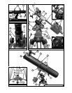
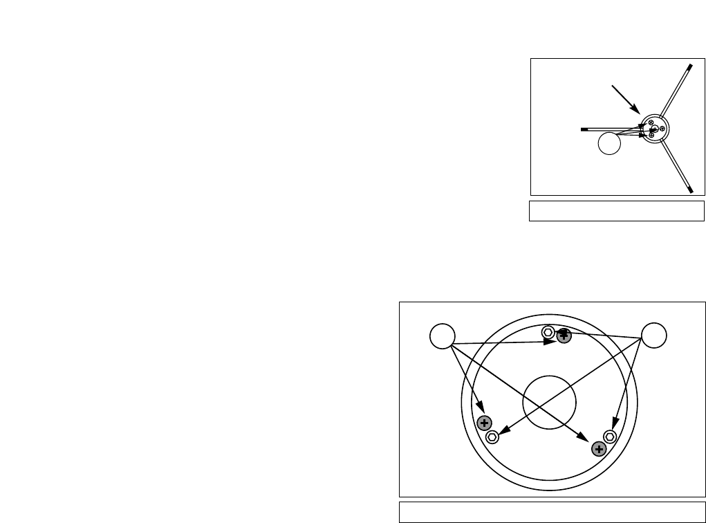
To inspect the view of the mirror collimation, look down the focuser
drawtube with the eyepiece removed. The edge of the focuser drawtube
(1, Fig. 7), will frame the reflections of the primary mirror with the 3 mirror
clips (2, Fig. 7), the diagonal mirror (3, Fig. 7) , the spider vanes (4, Fig.
7), and your eye (5, Fig. 7). Properly aligned, all of these reflections will
appear concentric (i.e., centered) as illustrated in Fig. 7.
Any deviation from the concentric reflections will require adjustments to
the diagonal assembly (Fig. 5), and/or the primary mirror cell (Fig. 6).
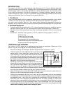
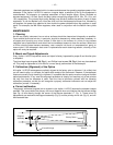
b. Diagonal holder adjustments
If the diagonal mirror (1, Fig. 8) is centered in the drawtube (2, Fig. 8), but the primary mirror is only
partially visible in the reflection (3, Fig. 8), the 3 Phillips-head diagonal tilt screws (1, Fig. 5. Note: To
adjust these screws you must first remove an adhesive backing) must be unthreaded slightly to the
point of where you can tilt the diagonal holder (3, Fig. 5) from side-to-side by grasping the diagonal
holder with your hand and tilt until you see the
primary mirror become as centered in the
reflection of the diagonal mirror as possible. Once
you are at the best position, thread in the 3
Phillips-head diagonal tilt screws to lock the
rotational position. Then, if necessary, make
adjustments to these 3 Phillips-head screws to
refine the tilt-angle of the diagonal mirror until the
entire primary mirror can be seen centered within
the diagonal mirror reflection. When the diagonal
mirror is correctly aligned, it will look like Fig. 9.
(Note: the primary mirror is shown out of
alignment.)
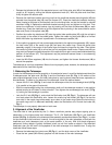
c. Primary mirror adjustments
If the diagonal mirror (1, Fig. 9) and the reflection of the primary mirror (2, Fig. 9) appear centered
within the drawtube (3, Fig. 9), but the reflection of your eye and the reflection of the diagonal mirror
(4, Fig. 9) appear off-center, you will need to adjust the primary mirror tilt Phillips-head screws of the
primary mirror cell (3, Fig. 6). These primary tilt screws are located behind the primary mirror, at the
lower end of the main tube. See Fig. 4. To adjust the primary mirror tilt screws, first unscrew several
turns, the 3 hex-head primary mirror cell locking screws (2, Fig.6) that are next to each primary mirror
tilt Phillips-head screw. Then by trial-and-error, turn the primary mirror tilt Phillips-head screws (3, Fig.
6) until you develop a feel for which way to turn each screw to center the reflection of your eye. Once
centered, as in Fig. 7, turn the 3 hex-head primary mirror cell locking screws (2, Fig. 6) to relock the
tilt-angle adjustment.
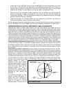
d. Star testing the collimation
With the collimation performed, you will want to test the accuracy of the alignment on a star. Use the
MA 25mm eyepiece and point the telescope at a moderately bright (second or third magnitude) star,
then center the star image in the telescope’s field-of-view. With the star centered follow the method
below:
• Bring the star image slowly out of focus until one or more rings are visible around the central disc.
If the collimation was performed correctly, the central star disk and rings will be concentric circles,
with a dark spot dead center within the out-of-focus star disk (this is the shadow of the secondary
mirror), as shown in Fig. 10C. (An improperly aligned telescope will reveal elongated circles (Fig.
10A), with an off-center dark shadow.)
• If the out-of-focus star disk appears elongated (Fig. 10A), you will need to adjust the primary mirror
Phillips-head tilt screws of the primary mirror cell (3, Fig. 6).
• To adjust the primary mirror tilt screws (3, Fig. 6), first unscrew several turns the 3 hex-head
primary mirror cell locking screws (2, Fig. 6), to allow free turning movement of the tilt knobs.
• Using the flexible cable controls (3 and 4, Fig. 1), move the telescope until the star image is at
the edge of the field-of-view in the eyepiece, as in Fig. 10B.
2
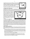
Fig. 5: Diagonal Assembly.
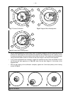
3
2
Fig. 6: Primary Mirror Cell.
1
Remove
adhesive
backing