


3-1. INTRODUCTION
This unit is designed for occasional homeowner use and
should not be used for commercial purposes or subjected
to heavy continuous use.
Your new chain saw can be used for a variety of projects
such as cutting firewood, making fence posts, felling small
trees, limbing, pruning at ground level, and light carpentry.
Cut only wood or wood products with your saw.
3-2. ASSEMBLY REQUIREMENTS
Your new chain saw will require adjustment of chain and fill-
ing the oil tank with lubricating oil before the unit is ready
for operation. Do not start the saw motor until the unit is
properly prepared. Read all instructions carefully. Do not
install any other size bar and chain than what is recom-
mended for your model.
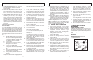
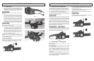
3-3. GUIDE BAR / SAW CHAIN INSTALLA-
TION
CAUTION
Disconnect the chain saw from power souce before check-
ing or adjusting the chain saw tension.
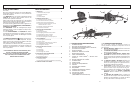
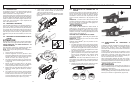
TO INSTALL GUIDE BAR & SAW CHAIN:
These instructions are for replacing a bar. The unit is fully
assembled when shipped.
NOTE : Always wear heavy gloves when handling the saw
chain.
1. Place power unit on flat surface.
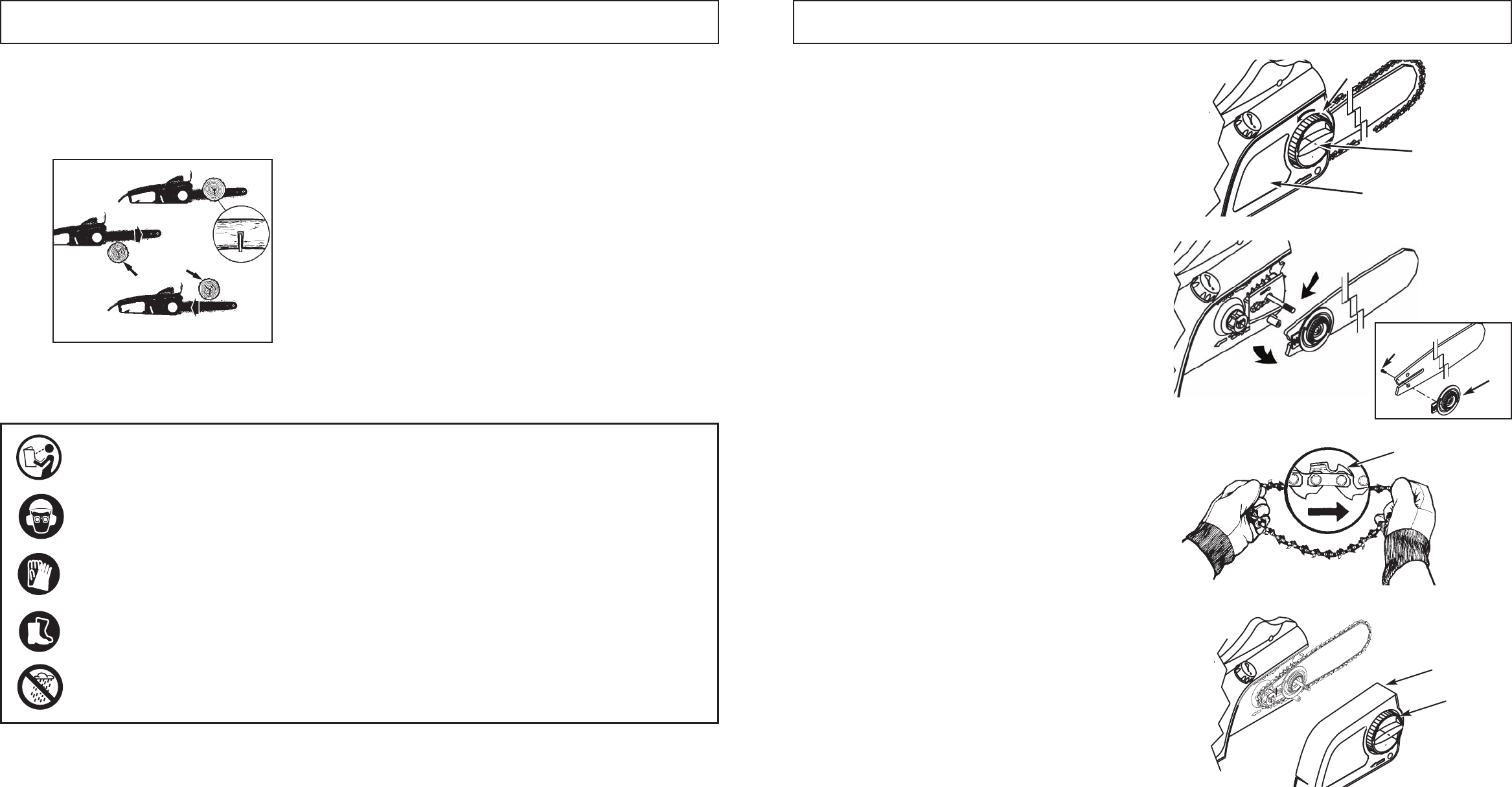
2. Loosen knob (B) slightly by turning knob counter-
clockwise and then turn the chain tension ring (C)
counter-clockwise to relief chain tension. To remove
the sprocket cover (A), turn knob (B) counter-clock-
wise. (Fig. 3-3A)
3. Remove saw chain form around the guide bar and the
sprocket. Slide the guide bar, with tension plate (D)
attached, from the unit. (Fig. 3-3B)
4. Remove screw (C) from the tension plate (D) to
remove it from the old bar and attach it to the new bar.
(Fig. 3-3B)
5. Spread the chain out with the cutting edges (E) of the
chain pointing in the DIRECTION OF ROTATION.
(Fig. 3-3C)
6. To fit the chain links into the groove on the guide bar,
turn the tension plate (D) counter-clockwise to the
end. Install the chain and bar on the power unit, turn
the tension plate (D) clockwise and then put the side
cover (A) on. (Fig. 3-3D)
7. Turn the knob clockwise, adjust the chain tension ring
(F) and then tighten the knob. After running the chain
saw for one(1) hour - retension the chain, if needed,
based on figure 3-4A.
9
3 - ASSEMBLY INSTRUCTIONS
3-3A
A
B
C
3-3B
C
D
3-3C
E
3-3D
A
F
8
2 - SAFETY PRECAUTIONS
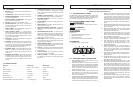
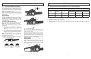
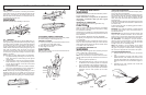
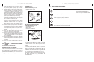
THE PUSH (PINCH-KICKBACK) AND PULL
REACTIONS (Figure 2-5B)
A = Pull
B = Solid objects
C = Push
KICKBACK may occur when the NOSE or TIP of the guide
bar touches an object, or when wood closes in and pinch-
es the saw chain in the cut.
Tip contact in some cases may cause a lightening-fast
reverse reaction, kicking the guide bar up and back toward
the operator.
PINCHING the saw chain along the BOTTOM of the guide
bar may PULL the saw forward, away from the operator.
(See Fig. 2-5B “A”)
PINCHING the saw chain along the TOP of the guide bar
may PUSH the guide bar rapidly back toward the operator
(See Fig. 2-5B “C”).
Any of these reactions may cause you to lose control of the
saw, which could result in serious personal injury.
2-5B
A
C
B
B
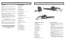
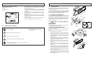
2-6. INTERNATIONAL SYMBOLS
Wear head, eye and hearing protection
Wear gloves to protect your hands
Wear safety boots to protect against electric shock
To reduce risk of electric shock, do not expose unit to water or
operate unit on wet ground.
Read User Manual.
Use of these personal safety items is
highly recommended to reduce the risk
of accidental injury.