


8 9
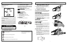
TO INSTALL SAW CHAIN:
WARNING
Always wear heavy duty gloves when handling saw chain
or making sa
w chain adjustments.
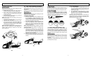
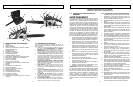
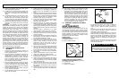
1. Spread chain out in a loop with cutting edges (A)
pointing CLOCKWISE around loop (Figure 3-3F).
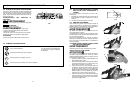
2. Slip the chain around the sprocket (B) behind the
clutch (C). Make sure the links fit between the sprock-
et teeth (Figure 3-3G).
3. Guide the drive links into the groove (D) and around
the end of the bar (Figure 3-3G).
NOTE: The saw chain may droop slightly on the lower part
of bar. This is normal.
4. Pull guide bar forward until chain is snug. Ensure all
drive links are in the bar groove.
5. Install the clutch cover making sure the tang is posi-
tioned in the lower hole in the guide bar. Make sure
the chain does not slip off of the bar. Install the bar
retaining nuts hand tight and follow tension adjust-
ment instructions in Section 3-4.
NOTE: The guide bar retaining nuts are installed only hand
tight at this point because saw chain adjustment is
required. Follow instructions in Section 3-4, Saw Chain
Tension Adjustment.
3-4. SAW CHAIN TENSION ADJUSTMENT
Proper tension of saw chain is extremely important and
must be checked before starting, as well as during any cut-
ting operation.
Taking the time to make needed adjustments to the saw
chain will result in improved cutting performance and pro-
longed chain life.
WARNING
Always wear heavy duty gloves when handling saw chain
or making saw chain adjustments.
TO ADJUST SAW CHAIN:
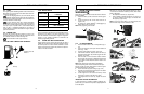
1. Hold nose of guide bar up and turn adjustment screw
(D) CLOCKWISE to increase chain tension. Turning
screw COUNTERCLOCKWISE will decrease amount
of tension on chain. Ensure the chain fits snugly all the
way around the guide bar (Figure 3-4A).
2. After making adjustment, and while still holding nose
of bar in the uppermost position, tighten the bar
retaining nuts securely. Chain has proper tension
when it has a snug fit all around and can be pulled
around by gloved hand.
NOTE: If chain is difficult to rotate on guide bar or if it binds,
too much tension has been applied. This requires minor
adjustment as follows:
A. Loosen the bar retaining nuts so it is finger tight.
Decrease tension by turning the bar adjustment screw
COUNTERCLOCKWISE slowly. Move chain back and
forth on bar. Continue to adjust until chain rotates
freely, but fits snugly. Increase tension by turning bar
adjustment screw CLOCKWISE.
B. When saw chain has proper tension, hold nose of bar
in uppermost position and tighten the bar retaining nut
securely.
3 - ASSEMBLY INSTRUCTIONS
CAUTION
A ne
w saw chain stretches, requiring adjustment after as
few as 5 cuts. This is normal with a new chain, and the
interval between future adjustments will lengthen quickly.
CAUTION
If saw chain is TOO LOOSE or TOO TIGHT, the sprocket,
bar, chain, and crankshaft bearings will wear more rapidly.
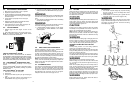
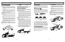
Study Figure 3-4B for information concerning correct cold
tension (A), correct warm tension (B), and as a guide for
when saw chain needs adjustment (C).
3-5. CHAIN BRAKE
®
MECHANICAL TEST
Your chain saw is equipped with a CHAIN BRAKE
®
that
reduces possibility of injury due to kickback. The brake is
activated if pressure is applied against brake lever when,
as in the event of kickback, operator’s hand strikes the
lever. When the brake is actuated, chain movement stops
abruptly.
WARNING
The purpose of the CHAIN BRAKE
®
is to reduce the possi-
bility of injury due to kickback; however, it cannot provide
the intended measure of protection if the sa
w is oper
ated
carelessly.
Alw
a
ys test the CHAIN BRAKE
®
bef
ore using y
our sa
w and
per
iodically while on the job
.
To Test CHAIN BRAKE
®
:
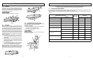
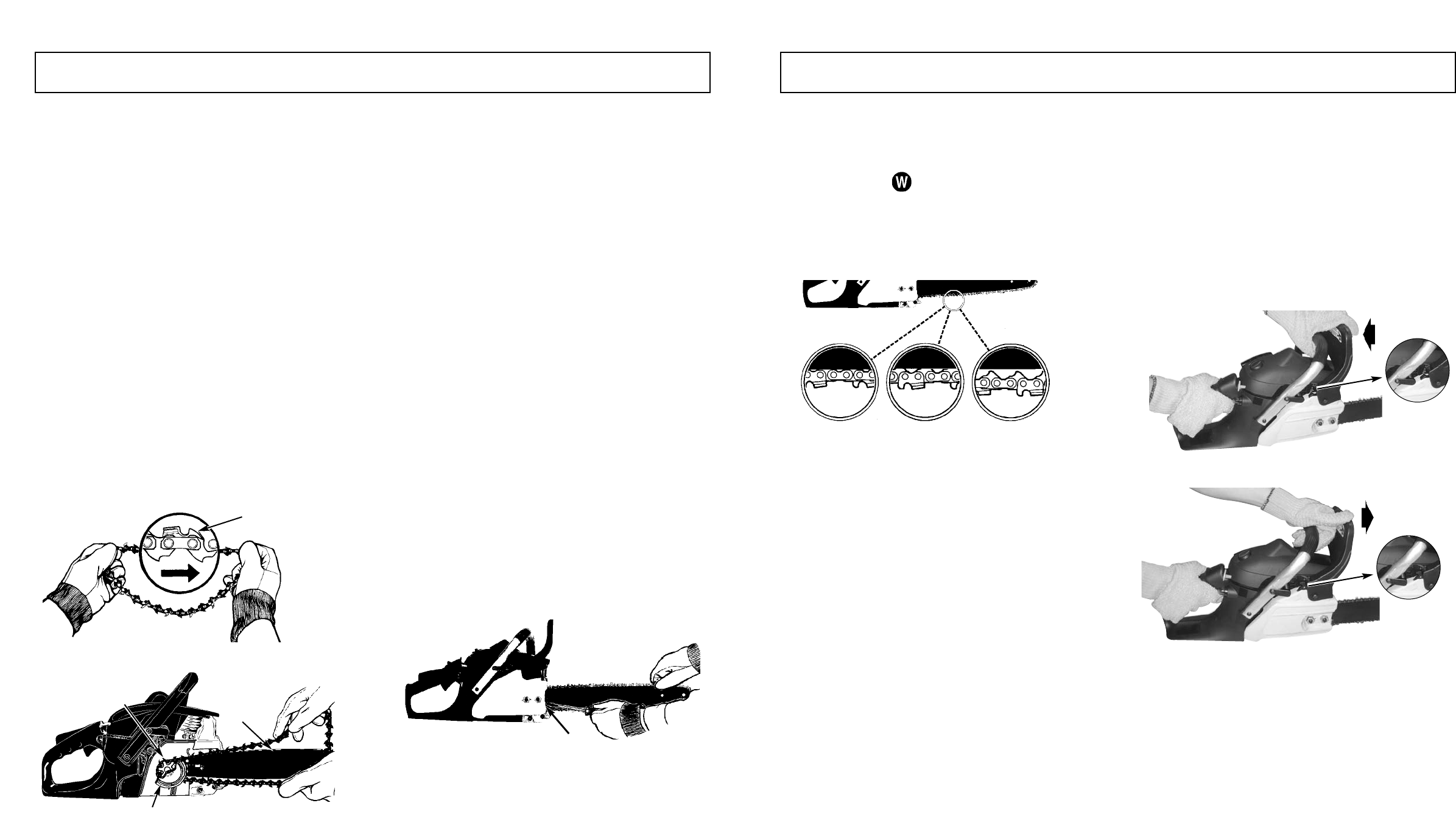
1.
The CHAIN BRAKE
®
is DISENGA
GED (chain can
move) when BRAKE LEVER IS PULLED BACK AND
LOCKED. Be sure the chain break latch is in the on
position. (Figure 3-5A).
2. The CHAIN BRAKE
®
is ENGAGED (chain is stopped)
when brake lever is in forward position and the chain
brake latch is in the off position. You should not be
able to move chain (Figure 3-5B).
NOTE: The brake lever should snap into both positions. If
strong resistance is felt, or lever does not move into either
position, do not use your saw. Take it immediately to an
Authorized Service Center for repair.
3 - ASSEMBLY INSTRUCTIONS
3-3F
3-3G
A
D
B
C
3-4A
D
3-4B
3-5A
3-5B
ON
A
C
B
OFF