


7
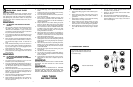
4-1. EXTENSION CORD
1. When using the power blower, an extension cord of
adequate size must be used for safety, and to prevent
loss of power and overheating. See Table 1.
2. The extension cord must be specifically designed for
outdoor use and marked “SW-A”, “SOW-A”, “STW-A”,
“STOW-A”, “SJW-A”, “SJOW-A”, “SJTOW-A”, “SJTW-
A”, or “SJTW”.
3. Inspect extension power cord for loose or exposed
wires and damaged insulation. If damaged, replace
before using power blower.
4. To reduce the risk of electric shock, this power blower
has a polarized plug (one blade is wider than the
other). This plug will fit in a polarized extension cord
only one way. If the plug does not fit fully in the exten-
sion cord, reverse the plug. If it still does not fit, do not
use that extension cord. Do not change the plug in
any way.
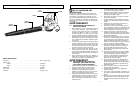
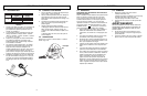
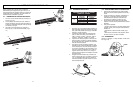
5. Secure the extension cord (A) to the power supply
cord (B) as shown in Figure 4-1A. Devices for retain-
ing extension cords may also be obtained at your local
hardware store.
4-2. OPERATING TIPS
1. Always work moving away from solid objects such as
walls, large stones, automobiles and fences.
2. Clean spaces with corners by starting in corners and
moving outward to straight areas to prevent an accu-
mulation of debris which could fly into face.
3. Be careful when working near valuable plants. The
force of air could damage tender plants.
4. Uses for your blower:
• Sweeping debris or grass clippings from driveways,
sidewalks, patios, parks, parking lots, barns, etc.
• Gathering grass clippings, straw or leaves into piles.
• Removing debris from corners, around joints and
between bricks.
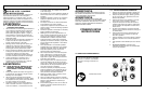
4-3. SWITCH
Press “o” Off, “1” Low Speed, “2” High Speed. (Fig. 4-3A)
4 - OPERATING INSTRUCTIONS
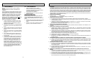
MINIMUM WIRE GAUGE RECOMMENDATIONS
VOLTS
EXTENSION CORD
LENGTH
WIRE SIZE
REQ
UIRED
120
25 f
eet / 7.5m 18 A.W.G.*
50 f
eet / 15m 16 A.W.G.*
100 f
eet / 30m 16 A.W.G.*
*
American Wire Gauge
Table 1
4-1A
B
A
4-3A
Switch
6
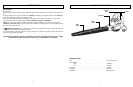
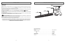
3 - ASSEMBLY INSTRUCTIONS
Remove blower from carton and examine it thoroughly to
make sure it is not damaged.
This electric blower requires
no tools for assembly. Read your User manual carefully
before assembly and operation.
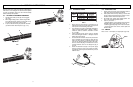
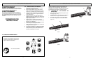
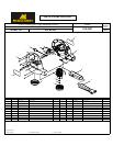
3-1. BLOWER ATTACHMENT ASSEMBLY
1. Pull the blower tube (A) from (B), till it’s engaged.
(Fig. 3-1A)
2. With a slight twisting motion, slide the larger width
end of the blower tube, with the cut-out notch on top,
into the blower outlet until it clicks in place.
3. To pull out the blower tube just press the red button
(C) and the blower tube will pull out. (Fig. 3-1C)
3-1A
B
A
3-1B
3-1C
C