


15
SERVICE AND ADJUSTMENTS
REPLACING THE LINE
For unit to o perate properly, the cutting line
should be replaced when line becomes worn to
less than 3 inches (7.5 cm) in l ength from the
edge of the line exit tunnels on each side of the
cutting head.
1. Remove and discard worn line before
installing new line.
2. Use only 0.115 inch (3 mm) diameter cut
length line.
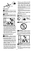
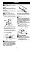
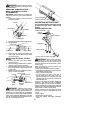
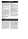
3. Insert one end of the line through the
positioning tunnel.
4. Continue to feed line through tunnel until
line is centered (leaving equal amounts
on each side). See illustration below.
Positioning
tunnel
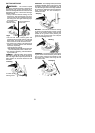
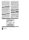
5. Insert ends of line one at a time through
the line exit tunnels.
6. Pull the line and make sure the line is ex-
tended fully through the tunnels.
Line exit
tunnel
Line exit
tunnel
7. Correctly installed line will be the same
length on both ends.
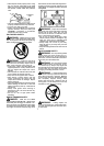
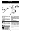
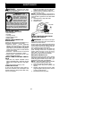
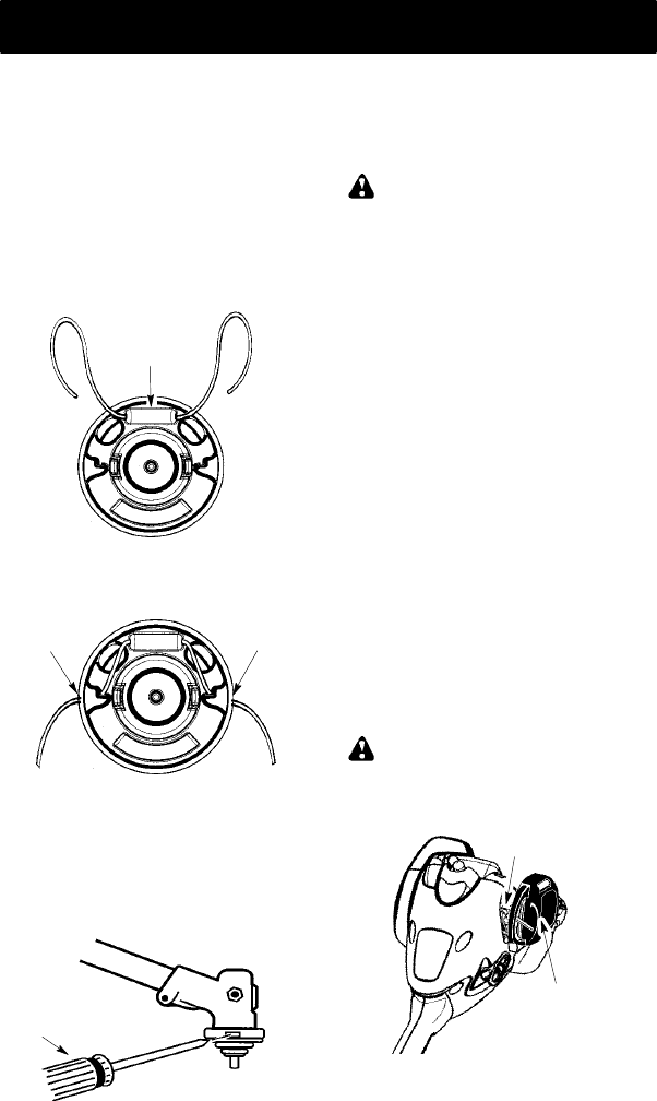
REPLACING THE CUTTING HEAD
1. Align hole in the dust cup with the hole in
the side of the gearbox by rotating the
dust cup.
2. Insert a small screwdriver into aligned
holes. This will keep the shaft from turning
while removing andinstalling trimmer head.
Screwdriver
3. While holding the screwdriver in position,
remove trimm er head by tu rnin g clockwise.
4. Thread replacement trimmer head onto
the shaft b y turning counterclockwise.
Tighten until secure.
5. Remove the screwdriver.
CARBURETOR IDLE SPEED
ADJUSTMENT
WARNING: Keep others away when
making idle speed adjustments. The trimmer
head, blade or any optional attachment will be
spinning during most of this procedure. Wear
your protective equipment andobserve all safe-
ty precautions. After making adjustments, the
trimmer head, blade or any optional attachment
must not move/spin at idle speed.
The carburetor has been carefully set at the
factory.Adjustments may benecessary ifyou
notice any of the following conditions:
S Engine will not idle when the throttle is
released.
S The trimmer head, blade or optional
attachment moves/spins at idle.
Make adjustments with the unit supported so
the cutting attachment is off the ground and
will not make contact with any object. Hold
the unitby hand while runningandmakingad-
justments. Keep all parts of your body away
from the cutting attachment and muffler.
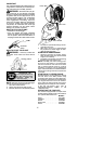
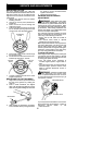
To adjust idle speed:
Allow engine toidle. Adjust speed untilengine
runs without trimmer head, blade or optional
attachment moving or spinning (idle too fast)
or stalling (idle speed too slow).
S Turn idle speed screw clockwise to
increase engine speed if engine stalls or
dies.
S Turn idle speed screw counterclockwise to
decrease engine speed if trimm er head,
blade or optional attachment moves or
spins at idle.
WARNING: Recheck the idle speed
after each adjustment. The trimmer head,
blade or optional attachment must not m ove
or spin at idle speed to avoid serious injury to
the operator or others.
Idle Speed Screw
Air Filter Cover
If you require further assistanceor areunsure
about performing this procedure, contact an
authorized service dealer or call
1--800--554--6723.