


21
SERVICE AND ADJUSTMENTS
00811
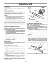
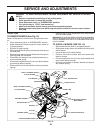
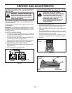
TO REPLACE MOTION DRIVE BELT
(See Fig. 22)
Park the tractor on level surface. En gage parking brake.
For as sis tance, there is a belt installation guide decal on
bottom side of left footrest.
BELT REMOVAL -
• Remove mower (See “TO RE MOVE MOWER” in this
section of manual).
NOTE: Observe entire motion drive belt and position of all
belt guides and keepers.
• Remove belt from stationary idler and clutching idler.
• Remove belt downward from around en gine pulley.
• Pull belt slack toward rear of trac tor. Remove belt
upwards from transaxle pulley by de fl ect ing belt keep-
ers.
• Remove belt from center span keeper and pull belt
away from tractor.
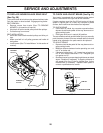
BELT INSTALLATION -
• Carefully work new belt down be tween transaxle belt
keepers and onto the input pulley.
• Slide belt into the center span keeper.
• Pull belt toward front of tractor and roll around the top
groove of engine pulley.
• Install belt through stationary idler and clutch ing
idler.
• Make sure belt is in all pulley grooves and in side all
belt guides and keep ers.
• Install mower (See “TO IN STALL MOWER” in this sec-
tion of manual).
FIG. 22
TRANSAXLE
PULLEY
STA TION ARY
IDLER
CLUTCHING
IDLER
ENGINE
PULLEY
CENTER SPAN
KEEPER
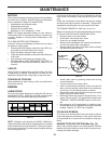
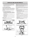
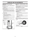
FIG. 23
00
663
RE TAIN ING RING
WASH ERS
SQUARE KEY (REAR
WHEEL ONLY)
AXLE COVER
TO REMOVE WHEEL FOR REPAIRS
(See Fig. 23)
• Block up axle securely.
• Remove axle cover, retaining ring and washers to allow
wheel removal (rear wheel contains a square key - Do
not lose).
• Repair tire and reassemble.
• On rear wheels only: align grooves in rear wheel hub
and axle. Insert square key.
• Replace washers and snap retaining ring securely in
axle groove.
• Replace axle cover.
NOTE: To seal tire punctures and prevent fl at tires due to
slow leaks, tire sealant may be purchased from your local
parts dealer. Tire sealant also prevents tire dry rot and
corrosion.
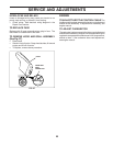
TO AD JUST STEER ING WHEEL ALIGN-
MENT
If steering wheel crossbars are not horizontal (left to right)
when wheels are positioned straight forward, remove steer-
ing wheel and reassemble per instructions in the Assembly
section of this manual.
FRONT WHEEL TOE-IN/CAMBER
The front wheel toe-in and camber are not adjustable on
your tractor. If damage has occurred to affect the front
wheel toe-in or camber, contact your nearest authorized
service center/department.