


1413
- Turn idle speed screw clockwise to increase engine
speed if engine stalls or dies.
- Turn idle speed screw counterclockwise to decrease
engine speed if trimmer head moves or spins at idle
speed.
- Engine will not idle when the throttle is released.
- The trimmer head moves/spins at idle speed.
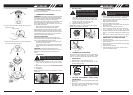
Make adjustments with the unit supported so the cutting
attachment is off the ground and will not make contact
with any object. Hold the unit by hand while running and
making adjustments. Keep all parts of your body away
from the cutting attachment and muffler.
Allow engine to idle. Adjust speed until engine runs
without trimmer head moving or spinning (idle speed too
fast) or engine stalling (idle speed too slow).
Refer to the ASSEMBLY section for blade replacement
instructions and illustrations.
WARNING: Recheck the idle speed after each
adjustment. The trimmer head must not move or spin at
idle speed to avoid serious injury to the operator or
others.
WARNING: Keep others away when making idle speed
adjustments. The trimmer head will be spinning during
most of this procedure. Wear your protective equipment
and observe all safety precautions. After making
adjustments, the trimmer head must not move/spin at idle
speed. The carburetor has been carefully set at the
factory. Adjustments may be necessary if you notice any
of the following conditions:
GB GB
Idle Speed Adjustment
• BLADE REPLACEMENT
• CARBURETOR ADJUSTMENT
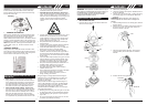
11. Reinstall the spool and cover onto the trimmer head.
Push until cover snaps into place.
• AIR FILTER
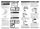
To Clean Air Filter:
1. Remove knob (A) holding air filter cover in place,
remove cover (B) and lift filter (C) from air box (Fig.
16).
2. Wash filter in soap and water. DO NOT USE PETROL!
3. Air dry filter.
4. Reinstall filter.
NOTE: Replace filter if frayed, torn, damaged or unable to
be cleaned.
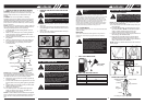
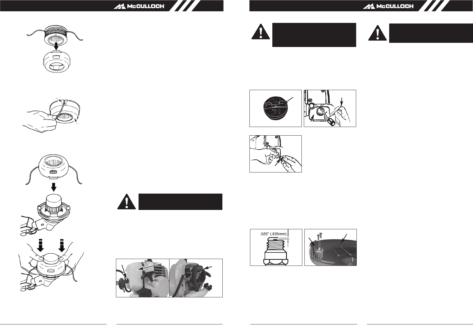
• Fuel Cap / Filter
1. Completely remove fuel cap (A) from fuel tank (B)
to be able to remove fuel filter (D) from tank. Use a
piece of wire (C) with a hook formed at the end to
pull filter out of tank. (Fig. 17A & Fig. 17B)
2. Pull filter (D) off with a twisting motion.
3. Replace fuel filter
(D). (Fig. 17C)
NOTE: Never operate the trimmer without the fuel filter.
Internal engine damage could result!
CAUTION: NEVER operate trimmer without
the air filter.The air filter must be kept clean.
If it becomes damaged, install a new filter.
CAUTION: Remove fuel from unit and store
in approved container before starting this
procedure. Open fuel cap slowly to release
any pressure which may have formed in fuel
tank.
• CARBURETOR ADJUSTMENT
The carburetor was pre-set at the factory for optimum per-
formance. If further adjustments are necessary, please
take your unit to the nearest Authorized Service Center.
• SPARK PLUG
1. Spark plug gap = .025" (.635mm) (Fig. 18).
2. Torque to 105 to 130 inch pounds (12 to 15 N•m).
Connect spark plug boot.
• CUTTING ATTACHMENT GUARD KNIFE
SHARPENING
1. Remove cutter knife (A) from cutting attachment guard
(B) (Fig. 19).
2. Place knife in a bench vise. Sharpen knife using a flat
file, being careful to maintain the angle of cutting
edge. File in one direction only.
• STORING A UNIT
1. Perform all the general maintenance recommended
in the Maintenance Section of your User Manual.
2. Clean exterior of engine, Output Shaft, cutting attach-
ment guard and cutting head.
3. Drain fuel from the fuel tank.
4. After fuel is drained, start engine.
5. Run engine at idle until unit stops.This will purge the
carburetor of fuel.
6. Allow engine to cool (approx. 5 minutes).
7. Using a spark plug wrench, remove the spark plug.
8. Pour 1 teaspoon of clean 2-cycle oil into the
combustion chamber. Pull starter rope slowly several
times to coat internal components. Replace spark
plug.
9. Store unit in a cool, dry place away from any source
of ignition such as an oil burner, water heater, etc.
• REMOVING A UNIT FROM STORAGE
1. Remove spark plug.
2. Pull starter rope briskly to clear excess oil from com-
bustion chamber.
3. Clean and gap spark plug or install a new spark plug
with proper gap.
4. Prepare unit for operation.
5. Fill fuel tank with new, fresh fuel / oil mixture. See
Fuel and Lubrication Section.
Fig. 17A Fig. 17B
A
C
B
Fig. 17C
D
Fig. 18 Fig. 19
WARNING: Failure to follow these steps
may cause varnish to form in the carburetor
and difficult starting or permanent damage
following storage.
E
F
Fig. 16
C
B
A
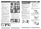
9. Place the spool in the cover as shown below.
10. Insert the ends of the lines through exit holes in the
sides of the cover.
Line exit hole
Cover