


7
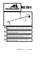
76 cm
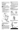
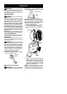
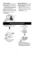
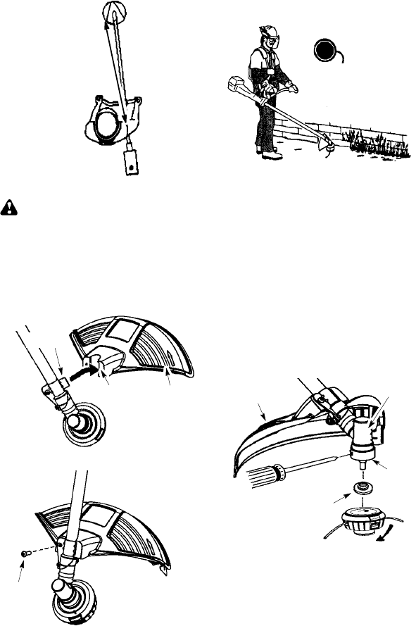
ATTACHING THE SHIELD
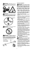
WARNING: Theshield must beprop-
erly installed. The shield provides partial
protection to theoperator andothers fromthe
risk of t hrown objects, andis equipped with a
linelimiter bladewhichcuts e xcess linetothe
proper length. The line limiter blade (on un-
derside of shield) is sharp and can cut you.
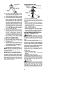
1. Insert bracket into slot on shield.
2. Pivot shield to align holes in shield and
bracket.
Slot
Shield
Bracket
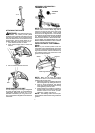
3. Secure shield to bracket with bolt.
Bolt
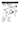
CONFIGURING YOUR UNIT
You canconfigure your uni t u sing acuttinghead
for grass and light weeds, or a weed blade for
cutting grass, weeds, and brush up to 1 cm in
diameter. To assemble your unit, go to the sec-
tion for the desired configuration and follow the
instructions.
ASSEMBLY INFORMATION --
TRIMMER HEAD
TRIMMER
HEAD
NOTE:Remove theblade before a ttaching t he
trimmer h ead. To remo v e b lade, align hole in
the dust cup with the hole in the side of the
gearbox by r otating the blade. Insert a small
screwdriver into alignedholes. This w illkeep
the shaft from turning while loosening the blade
nut. Remove blade nut by turning clockwise.
Remove the screwdriver . Remove both wash-
ers and blade. See INST ALLATION OF THE
METALBLADEforillustrations. Besuretostore
all parts and instructions for future use.
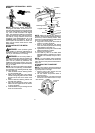
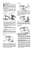
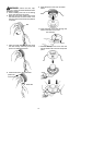
INSTALLATION OF THE TRIMMER
HEAD
NOTE:
If your unit has a plastic cover over
thethreads onthethreadedshaft,removethe
coveringto ex posethethreads.Beforeinstal-
lingthetrimmerhead, makesurethedustcup
and retaining washer are positioned on the
gearbox as shown below.
Retaining washer
Dust cup
Gearbox
Shield
NOTE: Make sure all parts are properly
installed as shown in the illustration before
installing the trimmer head.
1. Align holein t hedust cupwith thehole i nthe
side ofthe gea rbox by rotating t he dust cup.
2. Insert a small screwdriver into aligned
holes.Thiswillkeeptheshaftfromturning
while tightening trimmer head.
3. While holding thescrewdriver in pos ition,
thread trimmer head onto the shaft in the
direction shown on the decal (counter-
clockwise). Tighten until secure.
NOTE: The retaining washer must be posi-
tioned with the raised section facing toward the
gearbox.