


76
EN
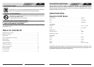
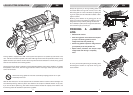
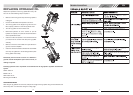
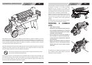
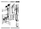
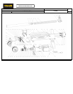
1. Log Pusher
2. Work Table
3. Wedge
4. Lift Handle
5. Support Leg
6. Log Retaining Plates
7. Switch
8. Motor
9. Pushbutton Box
10. Wheels for Minor Moving ONLY.
11. Hydraulic Control Lever
12. Control Lever Guard
13. Bleed Screw
14. Oil Drain Bolt w/ Dipstick
15. Max Pressure Limiting Screw
12
6
2
13
3
10
4
SET UP AND PREPARATION FOR OPERATION
1. Bolt the Support Leg to the Log Splitter, lift the log splitter by the handles at both ends and place it on
a 60 - 75cm high, stable, flat and level work surface.
2. Familiarize yourself with the controls and features of this log splitter in the illustrations.
11
5
7
8
9
1
14
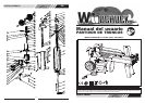
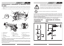
Before operating the log splitter, the Bleed Screw should be loosened by some rotations until air
can go in and out of the oil tank smoothly.
Air flow thru the Bleed Screw hole should be detectable during the log splitter is under operations.
Before moving the log splitter, make sure the Bleed Screw is tightened to avoid oil leaking from this
point.
FAILED TO LOOSEN THE BLEED SCREW WILL KEEP THE SEALED AIR IN
HYDRAULIC SYSTEM BEING COMPRESSED AFTER BEING DECOM-
PRESSED. SUCH CONTINUOUS AIR COMPRESSION AND DECOMPRES-
SION WILL BLOW OUT THE SEALS OF THE HYDRAULIC SYSTEM AND
CAUSE PERMANT DAMAGE TO THE LOG SPLITTER.
15
EN
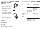
DO NOT ADJUST THE MAX PRESSURE LIMITING SCREW !.
Max pressure was set before the log splitter ex work and the max pressure limiting screw is sealed
with glue to ensure the log splitter works under pressure no more than 4 tons.The setting was done
by qualified mechanic with professional instruments.
Unauthorized resetting will cause the hydraulic pump fail to output enough splitting pressure or
RESULT IN SERIOUS INJURY AS WELL AS DAMAGE TO THE MACHINE .
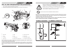
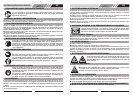
WIRING DIAGRAM
PLUMBING DIAGRAM
15