


ENGLISH - 6
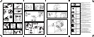
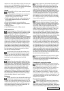
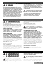
E4. Assembly/disassembly of line cutter head
Apply the nylon string head as shown in the illus-
tration: 1) Upper plate 2) Protection (not supplied
with all models) 3)Nylon string head. Tighten by
turning counterclockwise. As you tighten, hold the
nylon string head and plate still and insert the
wrench or screwdriver supplied in the holes in the
plate and gearbox; first turn the plate until the two
holes match.
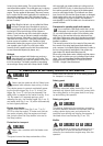
E5. Assembly/disassembly of grass cutter
blade
Apply the blade as shown in the illustration: a)
Upper plate with blade centering b) Protection
(not supplied with all models) c) Blade with word-
ing and direction arrow facing upward d) Lower
plate e) Fixed cup f) Blade fastening nut.
CAUTION! Do not use the nylon string
head guard extension with metal blades.
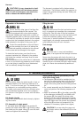
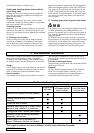
E6. Attachments fitting/removal (for split shaft
models only)
1) Loosen the joint knob first, then insert attach-
ment’s shaft into the shaft/attachment joint and
make sure that the locking pin (A) is secured in
one of its housings, finally lock firmly the joint
knob (B).
2) To remove the attachment from the power unit:
loosen the joint knob(1), push the locking pin
(2) and, keeping it pressed, remove attach-
ment’s shaft from the joint(3).
3) Every attachment manual explains through a
picture in which ways each attachment can be
assembled on the power unit: a configuration
is forbidden if crossed, if marked with “NO”
and/or the symbol ✗, or if it isn’t shown at all.
A configuration is allowed if marked with “OK”
and/or the symbol ✓.
The figure shows assembling configurations
allowed for the string head/grass blade attach-
ment (with the rules defined in the previous para-
graph, it is forbidden to assemble the string
head/grass blade attachment with the locking pin
in both left and right housings, allowing its
assembling in the upper housing only).
2 3 4 10
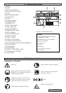
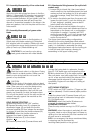
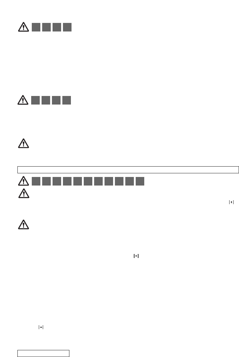
F. Starting and stopping the engine
CAUTION!
Start the brush cutter in a flat place. During
startup stand in a stable position. Make sure the
blade or nylon string head do not touch the
ground or any obstacles.
CAUTION!
Grip the knob of the starter with one hand
and hold the machine in a stable position with the
other. (Take care not to wind the starter string
around your hand) and pull slowly until you
encounter some resistance, then pull the cord
sharply and forcefully (to start the engine when
Do not pull the starter cord all the way and do not
release it abruptly against the machine as this
could damage it.
COLD ENGINE STARTING
1) Move stop switch to the “ON” position.
2) Depress the safety lever (S), squeeze the
accelerator trigger (A) and push the throttle
advance forwards (B). Now release the accelera-
tor trigger (A) and then the throttle advance (B).
WARNING: when the throttle advance is
engaged, the head or blade rotates.
3) Move choke lever (E) to the closed
position .
4) Press the primer bulb (C) several times until
you see fuel going back to carburetor through
pipe (D). Pull starter rope until engine fires once.
5) Move choke lever (E) to the open position
then pull starter rope until engine fires. Let engine
run for a few seconds holding the trimmer. Now
disengage throttle advance by pulling trigger
completely. Engine will now keep on running at
idle speed.
HOT ENGINE STARTING
STOP switch on START position I. Trigger on idle
position (released). Choke towards (open position
).
Press the primer bulb (C) several times until you
see fuel going back to carburetor through pipe
(D). Pull starter rope.
WARNING: when the throttle (B) advance is
engaged, the head or blade rotates.
6) ENGINE STOPPING
Press the stop switch moving it to STOP position
0.
WARNING: when the engine is switched off rotat-
ing parts, blade or nylon string head, will keep on
rotating for a few seconds. Hold the machine until
all parts come to a standstill.
N.B. In an emergency the above mentioned delay
in stopping may be shortened by
touching blade parallel on the ground.
1 5 6 7 8 9 10 11 12 14 17
2 3 4 10