


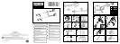


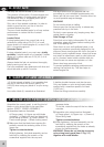


DANGER. Do not run engine without shaft
attached as clutch could fly off.
1) Insert the shaft (A) into the engine joint (B)
making the female squared end (C) inside
the joint mates with the male squared end
(D) of the shaft.
Rotate the shaft from right to left to obtain a
precise fit. Now tighten the locking bolt (E)
clockwise to ensure the shaft is held firmly in
the joint.
2) If the joint is not tightened onto the engine
housing, first make sure the shaft is fully and
correctly engaged up to the shank, then
tighten the 4 screws (A) in a criss-cross
sequence.
3) Assemble the eyelet (A) of the ground wire
onto the end of the throttle cable and install
the washer (B).
Insert the throttle cable into the cable mount
(C), install the second washer (B) and insert
the hexagonal nut.
4) Fit the end of the trigger cable connector (B)
into the slot on swivel (C).
5) Adjust the nut (D) of the trigger cable
connector so that the cable can easily slide
in the opening with a play of 1 mm before
operating the swivel (C).
Tighten now the hexagonal nut (E).
6) Stop switch (STOP) cable: fit the
connection.
G. ENGINE/SHAFT ASSEMBLY
9
A
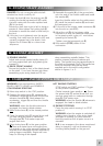
1) DOUBLE HANDLE
Adjust and secure double handle clamp 40
cm fromengine/shaft joint bytightening the
screws(C).
2) DELTA FRONT HANDLE
Secure the handle in front of the label placed
on the shaft 11 cm from the rear grip when
assembling nylon string head and 36 cm
when assembling metallic blades. This
position ensures optimum balance and
safety. The handle must be perpendicular to
the shaft as illustrated (Fig.2).The handle bar
must be mounted using all the items
supplied and in the exact configuration
shown in figures 1 or 2.
H. HANDLE ASSEMBLY
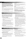
I. STARTING AND STOPPING THE ENGINE
WARNING. First read sections: SAFETY
RULES, SAFETY USAGE and SYMBOLS.
COLD ENGINE STARTING
1) Move stop switch to the “ON” position.
2) Depress the safety lever (S), squeeze the
accelerator trigger (A) and push the throttle
advance forwards (B). Now release the
accelerator trigger (A) and then the throttle
advance (B).
WARNING: when the throttle advance is
engaged, the head or blade rotates.
3) Move choke lever (E) to the closed position
.
4) Press the primer bulb (C) several times until
you see fuel going back to carburetor
through pipe (D). Pull starter rope until
engine fires once.
5) Move choke lever (E) to the open position
then pull starter rope until engine fires.
Let engine run for a few seconds holding the
trimmer. Now disengage throttle advance by
pulling trigger completely. Engine will now
keep on running at idle speed.
HOT ENGINE STARTING
STOP switch on START position I. Trigger
on idle position (released).
Choke towards (open position ). Press
the primer bulb (C) several times until you
see fuel going back to carburetor through
pipe (D). Pull starter rope.
WARNING: when the throttle (B) advance is
engaged, the head or blade rotates.
6) ENGINE STOPPING
Press the stop switch moving it to STOP
position 0.
WARNING: when the engine is switched off
rotating parts, blade or nylon string head,
will keep on rotating for a few seconds.
Hold the machine until all parts come to a
standstill.
N.B. In an emergency the above mentioned
delay in stopping may be shortened by
touching blade parallel on the ground.