


9 10
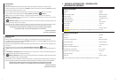
4- ASSEMBLY INSTRUCTIONS - INSTRUCCIONES DE ENSAMBLE
4-1A
ON
OFF
ON
OFF
4-1B 4-1C
B
A
C
D
E
F
G
E
N
G
L
I
S
H
• SAFETY RECOMMENDATIONS
In the interest of personal safety it is highly recommended when using the high pressure water cleaner to follow all
safety instructions
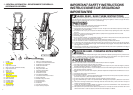
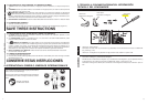
• ASSEMBLY AND START UP
1. Ensure pressure washer is at least 19 feet (6 meters) away from explosive vapors and combustible materials.
2. Insert the lance extension (A) into the trigger gun (B). Turn the lance extension (A) clockwise until tight. (Fig. 4-
1A)
3. Connect the high pressure hose (C) to high pressure outlet (D). (Fig. 4-1B)
4. Attach the Screw-type female connector (F) to water inlet (E). (Fig. 4-1C)
5. Connect the screw-type female connector (F) to male connector (G), which is linked to garden hose. (Fig. 4-1C)
6. Connect garden hose to the cold water source and turn water on completely. Inspect connections for leakages.
7. Insert power cord into power outlet. Pull the trigger (I) to allow water to flow through and eliminate any trapped
air. Wait for steady flow of water to discharge from the spray nozzle. Ensure the safety lock (H) is released before
pressing trigger (I). (Fig. 4-1D)
CAUTION
Water supply must be on and water discharge visible at nozzle before activating ON/OFF switch.
8. Turn on the machine by moving the switch to the ON position (J). (Fig. 4-1E). Your pressure cleaner is fitted with
Auto Start/Stop feature. This means the motor and pump will start only when the trigger lever is pressed and shut
off when it is released.
E
S
P
A
Ñ
O
L
• RECOMENDACIONES DE SEGURIDAD
Por seguridad personal, se recomienda encarecidamente seguir las recomendaciones de seguridad cuando se
utilice el limpiador de agua de alta presión.
• MONTAJE Y PUESTA EN MARCHA
1. Asegúrese de que el limpiador de presión está alejado al menos 6 metros (19 pies) de vapores explosivos y
materiales combustibles.
2. Inserte la prolongación de la lanza (A) en la pistola de activación (B). Gire la prolongación de la lanza (A) en el
sentido de las agujas del reloj hasta que apretada. (Figura 4-1A)
3. Una la manguera de alta presión (C) con la salida de alta presión (D). (Figura 4-1B)
4. Una el Conectador femenino screw-type (F) a la acometida de agua (E). (Figura 4-1C)
5. conecte el conectador femenino screw-type (F) con el conectador masculino ligado a la manguera (G) del jardín.
(Figura 4-1C)
6. Conecte la manguera de jardín a la toma de agua fría y abra el agua completamente. Inspeccione las conex-
iones por su hubiera fugas.
7. Enchufe el cable de alimentación a la toma de corriente eléctrica. Tire del disparador (I) para dejar que el agua
fluya y se elimine el aire atrapado. Espera a que salga un flujo constante de agua de la boquilla rociadora.
Asegúrese de que el bloqueo de seguridad (H) esté desactivado antes de presionar el disparador (I). (Figura 4-
1D)
PRECAUCION
SUMINISTRO DE AGUA DEBE ESTAR ABIERTA Y LA DESCARGA DE AGUA VISIBLE EN LA BOQUILLA ANTES
DE ACTIVAR EL INTERRUPTOR DE ENCENDIDO Y APAGADO.
8. Encienda la máquina colocando el ínterruptor en la posición de encendido (ON) (J). (Figura 4-1E). El limpiador
de presión cuenta con la función de Arranque y parada automáticos. Esto significa que el motor y la bomba sola-
mente se activarán cuando se presione la palanca del disparador y se desactivarán cuando dicha palanca se
suelte.
4-1D
4-1E
ON
O
FF
I
H
J
5-1A
A
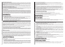
5- WORKING WITH DETERGENTS - TRABAJO CON LOS DETERGENTS
5-1B
B
5-1C
D
C
E
N
G
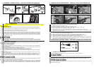
It is allowed for chemical tank ”Ι” and ”ΙΙ” to load different cleaning solutions.
1. Open the Upper tank cap (A). (Fig. 5-1A)
2. Refill directly cleaning (C) solution to chemical tanks (B). (Fig. 5-1B)
NOTE: For every 7 gallons of water pumped 1 gallon of chemical/cleaning solution will be used.
3. Tighten properly the tank cap (D) after the refilling. (Fig. 5-1C)
4. Switch to postion1 (E) for the choice of chemical tank ”
Ι”, postion2 for chemical tank ”ΙΙ”. (Fig. 5-1D)
5. Pull the spray nozzle (F) forward to adjust trigger gun in low pressure condition before the application of chemi-
cal tanks. (Fig. 5-1E & Fig. 5-1F)
5-1D
E
5-1E
F
5-1F
G
E
S
P
Se permite que el tanque químico ”Ι” y ”ΙΙ” cargue diversa soluciones de limpieza.
1. Habra el casquillo superior del tanque (A). (Figura. 5-1A)
2. Refilling que limpia directamente (C) la solución a los tanques químicos (B). (Figura. 5-1B)
NOTA: Para cada 7 galones de agua bombeó 1 galón de la solución chemical/limpiador será utilizado.
3. Tighten correctamente el casquillo del tanque (D) después de rellenar. (Figura. 5-1C)
4. Cambie posicion 1 (E) para la opción del tanque químico ”
Ι”, postion2 para el tanque químico ”ΙΙ”. (Figura. 5-1D)
5. Jale el inyector de aerosol (F) adelante para ajustar el arma del disparador en la condición de la presión baja
antes del uso de tanques químicos. (Figura. 5-1E & Figura. 5-1F)
6- OPERATING INSTRUCTIONS - INSTRUCCIONES DE OPERACION
E
N
G
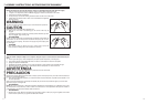
• WORKING WITH THE SPRAY PIPE
The spray angle can be adjusted from 0˚ to 30˚ by twisting the vario - nozzle (A).(Fig. 6-1A)
CAUTION
For cleaning easily damaged surfaces (e.g. paint. Vehicle tires), hold the spray tube at a greater distance from surface.
E
S
P
• TRABAJO CON TUBO ROCIADOR
El ángulo de rociada se puede ajustar de 0˚ à 30˚ por medio de apretar el vario - inyector (A). (Figura. 6-1A)
PRECAUCION
Para limpiar fácilmente la superficie dañada (por ejemplo pintura. Llanta de vehiculo), mantenga el tubo rociador a
una distancia mas grande.
6-1A
A