


ENGLISH - 6
and fasten it with the screw (E) (Make sure the
screws are tightened all the way (E) and are not
loosened by the vibrations. If necessary, tighten
them again).
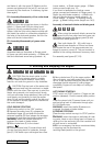
E4. Assembly/disassembly of line cutter head
Apply the nylon string head as shown in the illus-
tration: 1) Upper plate 2) Nylon string head.
Tighten by turning counterclockwise. As you
tighten, hold the nylon string head and plate still
and insert the wrench or screwdriver supplied in
the holes in the plate and gearbox; first turn the
plate until the two holes match.
E5. Assembly/disassembly of grass cutter
blade
Assemble blade as illustrated: a) Flange guard -
b) Upper cap with blade centering - c) Blade with
text and directional arrow facing upwards - d)
Lower washer - e) Fixed mower gauge - f) Blade
locking screw (length mm 16).
If you want to assemble the rotating mower
gauge, proceed as illustrated: a) Flange guard - b)
Upper cap with blade centering - c) Blade with
text and directional arrow facing upwards - d)
Lower washer - e) Spacer - f) Rotating mower
gauge - g) Blade locking screw (length mm 34,5).
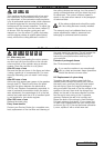
Assembly of sawtooth blade and blade guard
When using the sawtooth blade, remove the
guard for the line cutter head and grass cut-
ting blade and replace the flange guard (A) with
the sawtooth blade guard (H).
Saw tooth blades (24 - 80 tooth) have a
central base diametre of 20mm and there-
fore require the use of the appropriate size top
flange to ensure a correct fit. The part number is
detailed in the cutting attachment summary chart.
For assembly see figures (E7, E8).
2 3 4 10
2 3 4 10
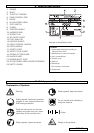
F. Starting and stopping the engine
CAUTION! Start the brush cutter in a flat
place. During startup stand in a stable
position. Make sure the blade or nylon string
head do not touch the ground or any obstacles.
CAUTION! Grip the knob of the starter with
one hand and hold the machine in a stable
position with the other. (Take care not to wind the
starter string around your hand) and pull slowly
until you encounter some resistance, then pull the
cord sharply and forcefully (to start the engine
when Do not pull the starter cord all the way and
do not release it abruptly against the machine as
this could damage it.
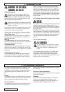
COLD ENGINE STARTING
1) Move stop switch to the “ON” position.
2) Depress the safety lever (S), squeeze the
accelerator trigger (A) and push the throttle
advance forwards (B). Now release the accelera-
tor trigger (A) and then the throttle advance (B).
WARNING: when the throttle advance is
engaged, the head or blade rotates.
3) Move choke lever (E) to the closed
position .
4) Press the primer bulb (C) several times until
you see fuel going back to carburetor through
pipe (D). Pull starter rope until engine fires once.
5) Move choke lever (E) to the open position
then pull starter rope until engine fires. Let engine
run for a few seconds holding the trimmer. Now
disengage throttle advance by pulling trigger
completely. Engine will now keep on running at
idle speed.
HOT ENGINE STARTING
STOP switch on START position I. Trigger on idle
position (released). Choke towards (open position
).
Press the primer bulb (C) several times until you
see fuel going back to carburetor through pipe
(D). Pull starter rope.
WARNING: when the throttle (B) advance is
engaged, the head or blade rotates.
6) ENGINE STOPPING
Press the stop switch moving it to STOP position
0.
WARNING: when the engine is switched off rotat-
ing parts, blade or nylon string head, will keep on
rotating for a few seconds. Hold the machine until
all parts come to a standstill.
N.B. In an emergency the above mentioned delay
in stopping may be shortened by
touching blade parallel on the ground.
1 5 6 7 8 9 10 11 12 14
2 3 4 10