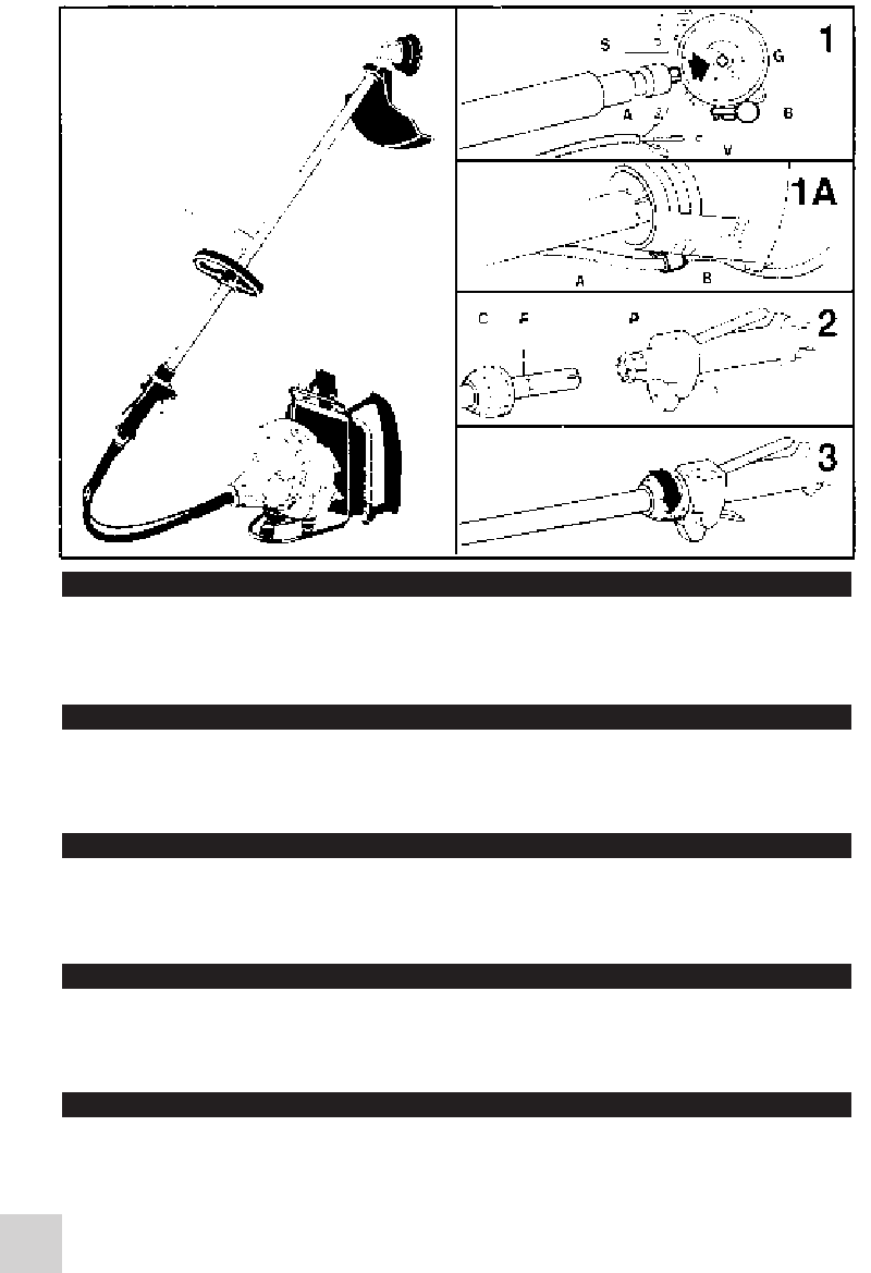
1 Insert the flexible drive shaft onto the engine connector (G). Ensure the
male square end of the shaft engaged firmly into the female square end of
the connector. Insert throttle cable and electrical wires (A) into the
retaining guide (B) far enough to allow the necessary connections to
be made (see Fig. 1A).
Tighten screw (V) ensuring it locates correctly into its opening (S). Now the
shaft is firmly fixed in the connector.
2 Pull the plastic ring nut (C) away from the end of the rigid tube turning it
counterclockwise if necessary. Insert the rigid tube into the handle section
until the label (F) is aligned with the edge of the plastic threaded rim (P).
These procedures will ensure a correct fit between both male and female
connectors.
3 Tighten the ring nut (C) hand tight. Follow the standard instructions
mentioned earlier in this manual to connect the throttle cable and electric wires.
A
BACK-PACK BRUSHCUTTER
D
DECESPUGLIATORE SPALLEGGIATO
1 Insérez l’arbre flexible dans le joint moteur (G). Assurez vous que l’embout
carré mâle de l’arbre s’insère dans le carré femelle du joint. Insérer le câble
d’accélération et les cables électriques (A) dans la gaine de maintien (B)
jusqu’à ce que les câbles ressortent pour permettre la connexion, (voir Fig.
1A). Serrez la vis (V) en s'assurant qu'elle est correctement placée dans son
logement (S). Maintenant l’arbre est fermement fixé au joint.
2 Dévissez la frette en plastique (C) et enfilez-la sur l’arbre. Positionnez
l’arbre dans son siège à l’intérieur de la poignée jusqu’à ce que l’etiquette
d’arrêt (F) coïncide avec le bord de la couronne en plastique taraudée (P).
Ces opérations permettent aux embouts carrés mâle/femelle de s’insérer
entre eux.
3 Vissez la frette (C) à la main en la serrant à fond. Connexion cable
accélérateur et fils électriques: suivez attentivement les instructions
mentionnées dans le manuel.
B
DÉBROUSSAILLEUSE À DOS
1 Setzen Sie die biegsame Welle in die Motorkupplung (G) ein.Veem Sie
sich, daß sich das Vjerkantendstück der Welle in die Vjerkantmutter der
Kupplung einfügt. Führen Sie den Gasseilzug mit Elektro-Kabel (A) in der
Festhalte-Führung weit genügend hinein um eine nötige Verbindung zu
ermöglichen (siehe Fig. 1A). Schraube (V) muß sich korrekt in der Öffnung
(S) befinden. Jetzt ist die Welle fest mit der Kupplung verschraubt.
2 Lösen Sie die Plastiknutmutter (C) und setzen Sie sie auf die Stange.
Lagem Sie die Stange in ihrem Sitz im Griffinnem, bis das Feststelletikett
(F) mit dem Rand des Plastikgewindekranzes übereinstimmt (P). Dies
ermöglicht eine richtige Verbindung von Endstück und Mutter.
3 Ziehen Sie von Hand die Nutmutter (C) fest an. Verbindung von
Gasleitung und Elektroleitungen: Halten Sie sich genauestens an die
Anweisungen des Handbuches.
C
MOTORSENSE - RÜCKENGERÃT
E
DESBROZADOR CON SOPORTE DORSAL PARA EL MOTOR
1 Innestate I’albero flessibile nel giunto motore (G). Assicuratevi che il
terminale quadrato maschio dell’albero vada ad innestarsi nel quadrato
femmina del giunto. Infilate facendo scorrere l’assieme filo gas e fili
elettrici (A) nella fascetta di fermo (B) sino a consentire i collegamenti
necessari (vedere Fig. 1A). Avvitate la vite (V) assicurandovi che si posizioni
correttamente nella sua sede (S). Ora l’albero é saldamente fissato al giunto.
2Svitate la ghiera in plastica (C) ed infilatela sull’asta. Alloggiate l’asta nella sua
sede all’interno dell’impugnatura sino a quando l’etichetta di fermo (F) va a
coincidere con il bordino della corona in plastica filettata (P). Queste operazioni
permettono ai terminali quadrati maschio/femmina di innestarsi fra loro.
3 Avvitate manualmente la ghiera (C) serrando fino in fondo. Collegamento
filo gas e fili elettrici: attenetevi scrupolosamente alle istruzioni riportate
all’interno del manuale.
1 Ensamble el eje flexible en el acoplamiento motor (G). Asegúrese de que el
extremo cuadrado macho del eje se inserla en el cuadrado hembra del
acoplamiento. Enfilar consuntamente el cable de gas y el cable electrico
(A) atraves de la guia (B) hasta conseguir el acoplamiento necesario,
(ver Fig. 1A). Apretar el tornillo (V) asegurándose que entra correctamente
en su alojamiento (S). Ahora el eje está firmemente fijado en el acoplamiento.
2 Desatornille la virola de plástico (C) y colóquela en el eje. Ponga el eje en
su asiento en el interior de la empuñadura hasta que la etiqueta de paro
(F) vaya a coincidir con el borde de la corona de plástico enroscada (P).
Todas estas operarciones permiten que los extremos cuadrados
macho/hembra se inserten entre ellos.
3 Atornille con los dedos la virola (C) aprietándola. Conexión cable
acelerador y cables eléctricos: aténgase estrictamente a las instrucciones
del manual.
88
ELITE 55-88 nuova imp 248734 29-11-2001 15:26 Pagina 88


