


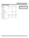
8
118679
PORTABLE GASOLINE GENERATORS
R
1
2
0
/
2
4
0
V
T
W
IS
T
L
O
C
K
1
2
0
V
T
W
I
S
T
L
O
C
K
1
2
0
V
G
F
C
I
1
2
0
V
V
O
L
T
A
G
E
H
O
U
R
M
E
T
E
R
A
U
T
O
-
I
D
L
E
R
E
S
E
T
R
E
S
E
T
R
E
S
E
T
R
E
S
E
T
O
F
F
O
N
S
E
L
E
C
T
O
R
1
2
0
O
N
L
Y
1
2
0
+
2
4
0
R
E
S
E
T
T
E
S
T
E
N
M
0
0
0
0
0
0
0
5
H
O
U
R
S
1
/1
0
E
F
FUEL
STANDBY
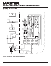
INSTALLATION
TO HOME OR
BUILDING
WARNING: The electrician
must install a double-throw
transfer switch. This isolates ex
-
isting electrical circuits from the
utility power line. If not isolated,
generator output will back-feed
into utility power line. This may
electrocute a power company line
repair person.
IMPORTANT: This generator will not
power your entire home. Most home utility
electric service is more than 60 amps. This
will exceed generator output. Only power
needed items during a power outage. Make
sure total wattage of electrical load does not
exceed rated wattage of generator.
You may need to use this generator as a
standby power source. During a power out
-
age, the generator will power selected items
in a building. Have generator and additional
wiring installed by a skilled, licensed electri-
cian. This is not a do-it-yourself job. Follow
all local codes.
WARNING: Have standby in-
stallation performed by a skilled,
licensed electrician. Do not let
anyone else wire into a utility
circuit. Personal injury, equip-
ment damage, or damage to home
could occur.
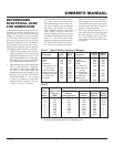
Ampere AWG for Length of
Load Cord in Feet
50' 100' 150'
2 18 18 18
3 18 18 18
4 16 16 16
5 16 16 16
6 16 16 14
8 16 14 12
10 16 14 12
12 14 14 12
14 14 12 10
16 12 12 10
20 10 10 8
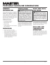
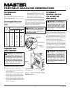
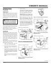
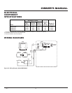
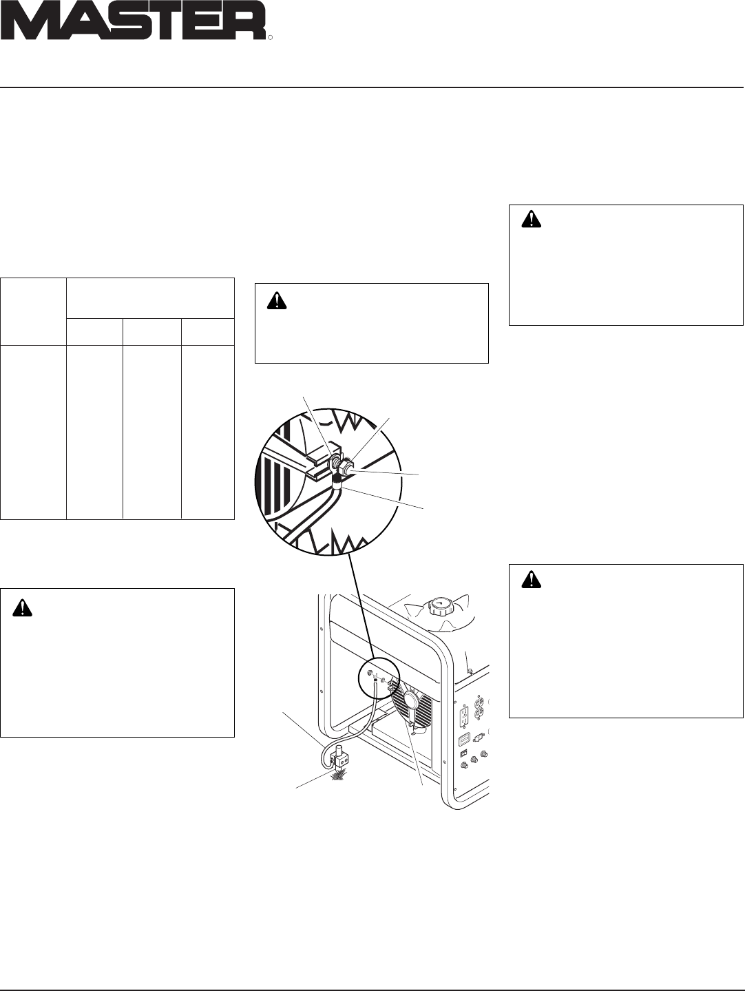
GENERATOR
GROUNDING
Ground
Wire
Alternator
Copper or Brass
Grounding Point
Figure 7 - Grounding Generator (Model
MGR4500I Shown)
EXTENSION
CORDS
Only use grounded extension cords. Be sure
to use extension cord with proper wire gauge
size. See chart below.
Recommended Minimum Wire
Gauges (AWG) for Extension
Cords
WARNING: For a grounding
point, do not use metal pipe be-
ing used to carry combustible
materials or gases.
Grounding generator helps prevent electric
shock from a ground fault condition. Follow
these steps to ground your generator:
1. Locate ground bolt on generator hous
-
ing (see Figure 7).
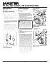
2. Loosen SEM nut on ground bolt. Note:
Do not remove SEM nut from bolt.
3. Attach a spade connector to the end of
a #10-8 stranded-copper ground wire.
4. Attach spade connector to ground bolt
between flat washer and SEM nut (see
Detail A in Figure 7).
WARNING: You must prop-
erly earth-ground generator be-
fore starting. This will help guard
against deadly electric shock. Only
use grounded plugs with genera-
tor. Only use grounded extension
cords. Only use three-wire or
double-insulated power tools.
1
2
0
/
2
4
0
V
T
W
IS
T
L
O
C
K
1
2
0
V
T
W
I
S
T
L
O
C
K
1
2
0
V
V
O
L
T
A
G
E
H
O
U
R
M
E
T
E
R
A
U
T
O
-
I
D
L
E
R
E
S
E
T
R
E
S
E
T
R
E
S
E
T
R
E
S
E
T
O
F
F
O
N
S
E
L
E
C
T
O
R
1
2
0
O
N
L
Y
1
2
0
+
2
4
0
E
N
M
0
0
0
0
0
0
0
5
H
O
U
R
S
1
/
1
0
E
F
FUEL
Ground Bolt
Flat Washer
Spade
Connector
SEMS Nut
Detail A
5. Drive grounding point into ground.
Note: Grounding point can be a stake,
grounding rod, or pipe. Grounding
point should be copper or brass.
6. Attach ground wire to grounding point.
You must supply the ground wire and ground-
ing point. These do not come with generator.
Follow the National Electrical Code and all
state and local codes. Consult your power
company or a licensed electrician.