


7
Assembly (continued)
HOW TO ASSEMBLE
LOWER HANDLES
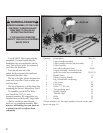
To identify part numbers, see
pages 6 and 18.
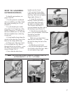
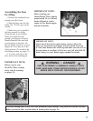
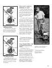
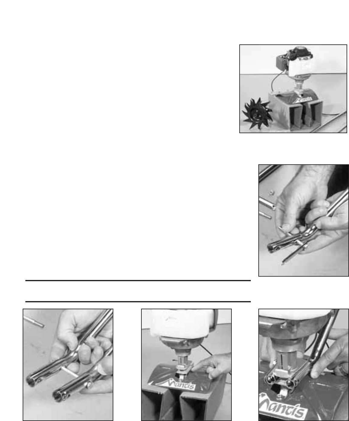
1. Use the protective cardboard
sleeve to stabilise your tiller. Stand
the engine assembly (no. 21) up.
(Picture 1)
2. Lay the handle parts within
easy reach. You’ll need one of the
handle clamps (no. 51) and one of
the lower handles (no. 6). Note that
the lower handles have a short leg
on one end.
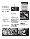
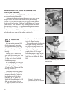
3. Fit the handle clamp along the
outside of the short leg. Line up the
holes on the clamp and the leg.
4. Choose one of the two 3-inch
(7.62 cm) bolts (no. 49). Slide it
through the first set of holes — near
the elbow where the lower handle
curves. (Picture 2 & 3)
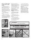
5. Now slide the other lower
handle onto the 3-inch
(7.62 cm) bolt. Fit the other
clamp onto this other handle’s
short leg. Add a nut and tighten
finger tight. (Picture 3)
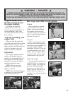
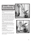
6. Locate the worm gear
housing. It starts just above —
and extends down through —
the tiller’s red fender guard.
You’ll notice that there’s a
recessed channel on either side of
the housing’s top. (Picture 4.)
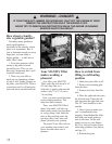
7. Take the lower handles that
you’ve just put together. Slide them
into the two recessed
channels.(Picture 5.)
Make sure you insert them
from the rear of the tiller . . . so that
the bolt fits along the back of the
housing.
8. Slide the second 3-inch
(7.62 cm) bolt through the second
set of holes in the short legs. Add a
nut and tighten finger tight.
Picture 1
Picture 2
Picture 3
Picture 4 Picture 5
NOTE: THE LOCK NUTS ARE STAMPED. FINGER TIGHT IS
APPROXIMATELY 1/2 TO 1-1/2 TURNS.