


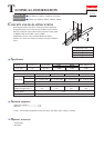
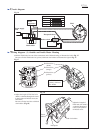

Circuit diagram
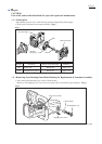
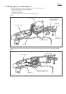
Wiring diagram- (1) Outside and Inside Motor Housing
P 7 / 8
Fig. 16
Fig. 17
Fig. 18
Color index of lead wire sheath
Black
White
Orange
Yellow
COM
Receptacle sleeve
NO
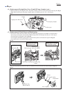
Pull the Field lead wires out of the commutator end of Motor housing as illustrated to left in Fig. 17.
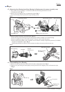
Be sure to fix the Field lead wire (yellow) with lead wire holders as illustrated to right in Fig. 17.
12
45
3
Main switch
Power supply
cord
Field
Field lead wire
(orange)
Field lead wire
(yellow)
Field lead wire
(black)
Fix Field lead wire
(yellow) with lead
wire holder.
Screw
M5x55
Receptacle
Lead wire holders
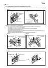
Adjust the length of
Field lead wire (black)
so that the Receptacle
comes to the position
of M5x55 screw.
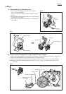
Noise
suppressor
Brake switch
Adjust the length of Field lead wire
(black) so that the Receptacle comes
to the position of M5x55 screw, the
field screw.
Be sure to fix the lead wire with lead
wire holders. (Fig. 18)
(to be continued to next page)