


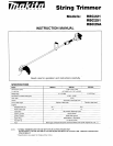
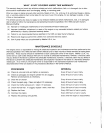

ENGINE STARTING AND STOPPING
PROCEDURES
Starting when the engine
is
cold
Use
the following procedure when the engine
is
cold,
or
after it
has
been stopped
for
longer than
5
minutes,
or
after
fuel
has
been added to the engine:
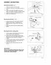
1.
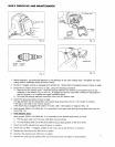
Slide the stop switch away from the "STOP" position
(Fig.
5).
2.
Gently push on the primer pump repeatedly
(7
-
10
times)
until
fuel
enters the primer pump (Fig.
6).
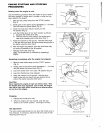
3.
Close the choke lever fully by moving it to the
[XI
position (Fig.
6).
4.
Lock
the throttle lever in the "start" position
as
follows:
i). Squeeze the throttle lever fully.
ii).
Hook
the lock fin to the notch in the throttle lever
case
while releasing the throttle lever (Fig.
7).
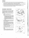
5.
Place
the machine on the ground. Hold the drive shaft
or
the grip with one hand, and give several strong pulls
to
the starter using the other hand.
6.
After the engine has started, open the choke lever fully
by moving it gradually
to
the
I$I
position.
7.
Release the throttle lever
fully.
Note:
The throttle lever
is
unlocked by squeezing it
slightly.
Restarting immediately after the engine has stopped.
1.
Slide the stop switch away from the "STOP" position
(Fig.
5).
2.
Gently push on the primer pump repeatedly
(7
-
10
times)
until fuel enters the primer pump (Fig.
6).
3.
Leave the choke lever in the open
1$1
position (Fig.
6).
4.
Leave the throttle lever fully
released.
5.
Place
the machine on the ground. Hold the drive
shaft
or
grip with one hand, and give several strong
pulls
to
the starter using the other hand.
CAUTION:
Never operate the engine at high rpm without load. With
the throttle lever fully squeezed and no load, the engine
rpm will be very high which could have an adverse effect
on the
life
of
the engine.
Stopping
1.
Release the throttle lever fully.
2.
When the engine rpm has lowered, push the stop
switch to the "STOP" position. The engine will stop.
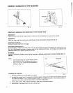
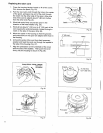
Idle adjustment
The nylon cutting head should not run when the throttle lever
is
fully released.
If
necessary,
adjust
the
idle
rpm using the idle
adjusting screw (Fig.
8).
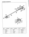
Stop
Position
'"0
Start
Position
7"
Fig.
5
I
I
Choke
lever
Fig.
6
Fig.
7
Idle
adjusting
screw
Fig.
8
7
F