


i
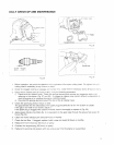
STORAGE
When storing the
machine
for
a icng time drain the fuel from the fuel tank and
cdrbLretor
as
follows
'
1
2
3
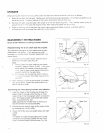
Drain
all
fuel
from
the fuel tank Gently
push
on the primer
pump
repeatedly
iintrl
all fuel
IS
expelled out of
the primer
pump
Properly dispose of the fuel
in
accordance
with
all
local laws
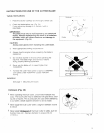
Remove the spark
aluy
and add a few drops of
oil
into
the spark
plug
hole
Then
pull
the starter geMy
to
assure
that
dn
oil
;ilm
coats the engine inside, then insert and tighten the
SD~
k
dug
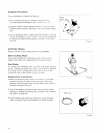
Clear
or
olow
any
dirt
or
dust
from the nylon cutting head and engine housing wpe them
with
an
oil-immersed cloth and store the machine
in
a
dry
location
REASSEMBLY
1NSTRUCTlONS
Brush
Cutter
RBC2.52
and
String Trimmer
RBC253
Reassembling
the
drive
shaft
and
the
engine.
The
shaft
and the engine on
this
machine
have been
assembled
in
the factory.
If
you remove the shaft
(example,
for
maintenavce) carefully reassemble
it
as
shown be
I
ow:
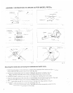
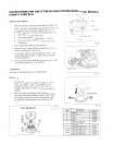
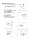
1.
Loosen
the
screws
M5x18 and insert the drive
shaft
into
the holder case
(Fig.
31).
Note:
i).
Always inserr the drive shaft into the holder
case
fully
(approx. 60mm; 2-3/8").
If
the inner
shaft resists
full
insertion
of
the
drive shaft,
try
to
insert
it
again while
slightly
rotating the
siqport
washer
on
the gear case.
ii).
5~2
caiitio~is
not
to
allow
the
switch cords
to
!:;:
;jinih;d
between the holder case and the
gt1i
end.
2.
After
making
scire
that the drive shaft
is
installed
fully
and properly. tighten the screws M5x18
to
secure the drive shaft.
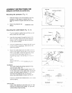
Connecting
the
wires
(String
Trimmer
only
RBC253)
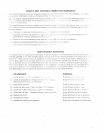
1.
Insert the nipple
of
the throttle
wire
through the
square hole
in
the
grip
until
it
fits
into an
inner
square hole
in
the moving
part
which
is
inside the
grip.
The
nipple
should
move
when
the
throttle
lever
is
squeezed
(Fig.
32).
Note:
Squeeze the throttle lever
to
make sure
that the throttle wire moves
smoothly.
2. Connect the
two
switch wires
to
the
engine wires
by
inserting one
into
the
other.
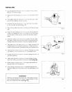
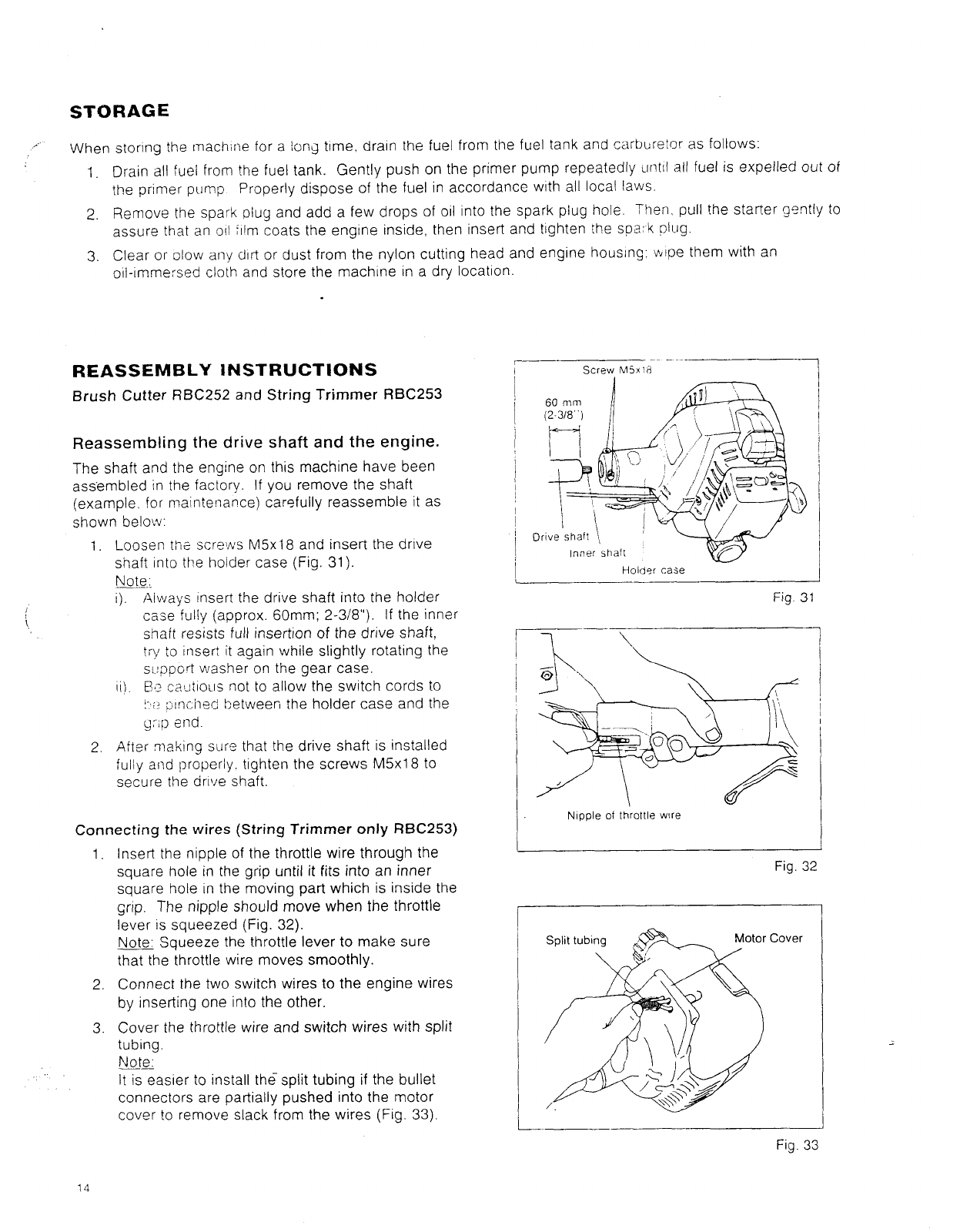
3. Cover the throttle
wire
and
switch
wires
with
split
tubing.
_-
Note:
It
is
easier
to
install
the
split
tubing
if
the bullet
connectors are partially pushed into the motor
cover
to
remove slack from the wires
(Fig.
33).
j
~
I
I
I
I
~
Hoidsr
case
Fig
31
i-
1
.
Nipple
of
throttle
wire
Fig.
32
Fig.
3:
14