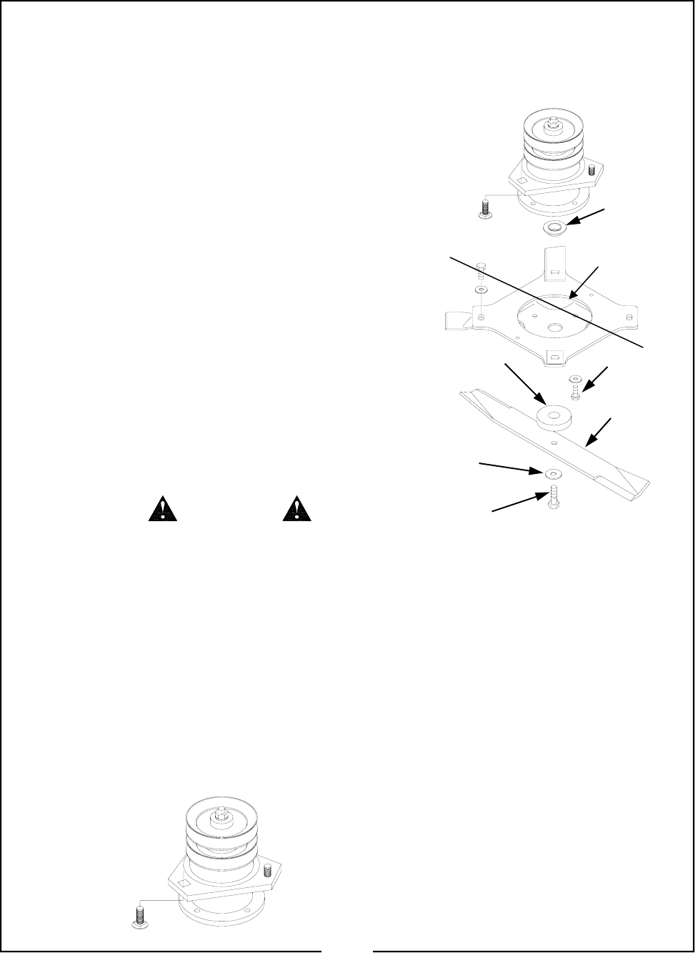
BLADE SPINDLE DISASSEMBLY
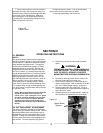
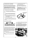
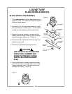
1. Using safety gloves, hold the lower blade and re-
move the 1/2" x 1-3/4” capscrew, Belleville washer,
blade and shaft washer.
2. Remove the (4) 3/8” capscrews holding the upper
disc assembly to the blade carrier. Lift the disc as-
sembly and shaft bushing off the spindle shaft.
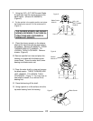
3. Support the spindle housing in a press with the
blade carrier turned up. Press the inner shaft top
bearing and upper sheave out. (Figure 3)
4. Remove the 5/8” locknut from the inner shaft and
press the sheave off.
5. Remove the woodruff key and top bearing.
USE SAFETY EYE PROTECTION
WHEN USING HAMMER AND
PUNCH TO PREVENT FLYING
PARTICLES FROM INJURING
EYES.
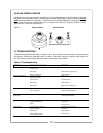
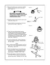
6. Using a blunt punch: unstake sheave from upper
end of outer shaft and unstake blade carrier from
lower end of outer shaft. (Use care so as not to
damage the threads.) (Figure 4)
CAUTION
LOCKE TURF
BLADE SPINDLE SERVICE
Figure 2
Shaft Bushing
Shaft Washer
(4) 3/8 x 3/4”
Capscrews
Lower Blade
Clockwise
Belleville
Washer
1/2 x 1-3/4”
Capscrew
Figure 4
19
Not Available
on the FP


