


8
OPTIMAX
BLOWER
ASSEMBLY
Blower Assembly Instructions
NOTE : Refer to parts lists, and illustrations on
Pages 14-17.
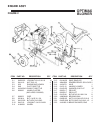
1. Install lower handles 15 on top of deck 17 & 18.
Secure with (4) cap screws 5/16-18 X 1-3/4 19,
(4) 5/16 at washers 16, and (4) 5/16-18 nylon
nuts 1, nger tight. (See Figure 2)
2. Install upper handle 6 with (4) 5/16-18 X 1-3/4
cap screws 19, (8) 5/16 washers 16, and (4)
5/16-18 nylon nuts 1, nger tight. Tighten lower
handle nuts and bolts. Tighten upper handle nuts
and bolts until the lower handle tubing pinches
the upper handle. It will be normal for the lower
handle tubing to crush slightly. (See Figure 2)
3. Attach brace 23 with (2) 5/16-18x2 cap screws 9,
(4) 5/16 washers 16, and (2) 5/16-18 nylon nuts
1. (See Figure 2)
4. Attach throttle cable 5 to upper handle 6 with
(1) 1/4-20 X 1-3/4” cap screw 8 and (1) 1/4-20
locknut 10 through hole on upper handle 6 on the
left handside. Connect throttle clip 4 to upper
handle (See Figure 2)
NOTE: Over tightening the screw on the left hand
mounted controls could cause damage to the
control.)
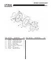
5. Tilt blower back on handle and install front wheel
bracket 17 over the three studs on lower front of
blower housing 2. Secure with (3) 5/16-18 ange
nuts 1. (See Figure 3)
6. Insert pneumatic wheel sleeve 19 in front
pneumatic wheel 18. Install pneumatic wheel
spacers 20 over the axle sleeve on both sides
of wheel and install in front wheel bracket 17.
Insert 3/8-16 X 5-1/2 axle bolt 16 through wheel
bracket and axle sleeve. Secure with 3/8-16 axle
nut 15. (See Figure 3)
ALL LITTLE WONDER BLOWER ENGINES
ARE SHIPPED WITHOUT OIL. WHEN FILLING
WITH OIL, USE SAE 30. REFER TO ENGINE
MANUFACTURES INSTRUCTION MANUAL FOR
PROPER ENGINE OPERATION INSTRUCTIONS.