


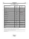

1
2
7
8
3 or 4
6
9
10
12
11
5
1
2
7
8
3 or 4
6
9
10
12
11
5
B-4
OPERATION
B-4
OUTBACK™ 185
®
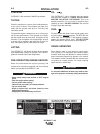
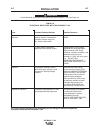
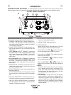
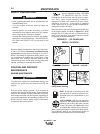
CONTROLS AND SETTINGS All welder/generator controls are located on the Output Control Panel.
Gasoline engine controls are mounted on the engine. See Figure B.1 and the figures in engine operation section.
WELDER/GENERATOR CONTROLS
See Figure B.1 for the location of the following features:
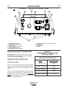
1. CURRENT CONTROL DIAL: Adjusts continuous cur-
rent output. The amperages on the dial correspond to
the approximate amperages needed for specific
Lincoln welding electrodes.
2. 30 AMP CIRCUIT BREAKER: Provide separate over-
load current protection for the 120 Volt and 240 Volt
Receptacles
3. WELD POSITIVE OUTPUT TERMINAL: Pro vides the
connection point for either the electrode holder or the
work cable. (Because the OUTBACK™ 185 is a DC
output machine, either output terminal can be used for
either cable.)
4. WELD NEGATIVE OUTPUT TERMINAL: Provides the
connection point for either the electrode holder or the
work cable. (Because the OUTBACK™185 is a DC
output machine, either output terminal can be used for
either cable.)
5. GROUND STUD: Provides a connection point for con-
necting the machine case to earth ground for the
safest grounding procedure.
6. CIRCUIT BREAKER: Provides overload protection for
weld output terminals.
7. CIRCUIT BREAKERS (2): Provide separate overload
current protection for the 120 volt and 240 volt recepta-
cles
8. 240 VOLT RECEPTACLE: Connection point for sup-
plying 250 volt power to operate one electrical device.
9. 120 VOLT DUPLEX RECEPTACLES (2): Connection
point for supplying 120 volt power to operate devices
needed for maintenance purposes.
OUTPUT PANEL CONTROLS
FIGURE B.1
10. HOUR METER: Records the time that the engine
has run for maintenance purposes.
11. ENGINE CHOKE: Engine starting aid.
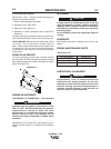
12. ENGINE SWITCH:
Used to start the engine, Select High Idle or Auto Idle
while the engine is running and stops the engine.
When placed in the “OFF” position, the ignition
circuit is de-energized to shut down the engine.
When held in the “START” position, the engine
starter motor is energized.
When in “HIGH IDLE” ( ) position, the engine
will run continuously at high idle.
When in “AUTO IDLE” ( / ) position, the
engine will run continuously and the idler operates as
follows:
• Welding
When the electrode touches the work, the welding
arc is initiated and the engine accelerates to full
speed. After welding ceases (and no auxiliary power
is being drawn), the engine will return to low idle
after approximately 10 to 14 seconds.
• Auxiliary Power
With the engine running at low idle and auxiliary
power for lights or tools is drawn (approximately 0-
150 watts or greater) from the receptacles, the
engine will accelerate to high speed. If no power is
being drawn from the receptacles (and not welding)
for 10-14 seconds, the idler reduces the engine
speed to low idle.