


B-3
OPERATION
B-3
POWER-ARC 5500
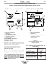
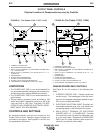
4. WELD OUTPUT TERMINAL (TO WORK) WITH 1/2
- 13 FLANGE NUT: Provides the connection point
for either the electrode holder or the work cable.
(Because the POWER-ARC 5500 is an AC output
machine, either output terminal can be used for
either cable.)
5. GROUND STUD: Provides a connection point for
connecting the machine case to earth ground for
the safest grounding procedure.
6. • 20 AMP CIRCUIT BREAKERS (2): Provide sepa-
rate overload current protection for the 120 volt
and 240 volt receptacles. (For codes 11182,
11187, 11215)
• 20 AMP CIRCUIT BREAKER: Provide separate
overload current protection for the 120 volt and
240 volt receptacles. (For codes 11403, 11404)
7. 20 AMP, 240 VOLT RECEPTACLE: Connection
point for supplying 240 volt power to operate one
electrical device.
8. 20 AMP, 120 VOLT DUPLEX RECEPTACLE:
Connection point for supplying 120 volt power to
operate one or two electrical devices.
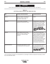
9. Tachometer / Hourmeter: (For Code 11215, 11404
Only)
Records engine speed in RPMs, engine running
time, and alerts the user to perform a specific
engine maintenance task by flashing correspond-
ing messages. If the message reads “Chg Oil”, the
user needs to change the oil in the engine. If the
message reads “SVC AIR-FiILTER”, the user
needs to clean or if necessary,change the air filter.
(See Honda Engine”s owners manual for more
information). After maintenance task is preformed,
the user is required to use the supplied Reset Tool
to cancel flashing message and resume normal
meter operation. (See page D-1 for futher details).
GASOLINE ENGINE CONTROLS
Refer to your engine manual for the location of the
following features:
1. FUEL SHUTOFF VALVE: Stops the flow of gaso-
line from the fuel tank to the carburetor. Should
be closed whenever you are finished using the
POWER-ARC 5500. Must be opened before you
start the engine.
2. FUEL TANK AND CAP: See TECHNICAL SPECI-
FICATIONS for capacity.
NOTE:
If you use any other alternate fuel tank or
supply, be sure to use a recommended in-
line fuel filter.
3. MUFFLER: Reduces engine noise output. Both
the Robin / Subaru and the Honda muffler serves
as a spark arrester.
See
SPARK
A
ARRESTER
in the
INSTALLATION
section of this manual.
4. “ON/
OFF Switch: A two position switch located
on the rear of the engine. In the “ON”(
I
) position,
the engine ignition circuit is energized and the
engine can be started by pulling the recoil rope
starter. In the “OFF”(
O
) po
sition, the electronic
ignition is grounded and the engine shuts down.
5. AIR CLEANER: Filters intake air to the carburetor.
See
ENGINE
M
MAINTENANCE
in the
MAINTE-
NANCE
section of the engine owner’s manual for
details about the specific type of air cleaner to
use.
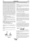
6. CHOKE: Provides a richer air/fuel mix-
ture for cold engine starting condi-
tions. See the topic ENGINE OPERA-
TION, below, for details on setting the
choke.
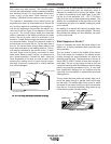
7. RECOIL STARTER: Manual, rope-type starter.
The handle position allows easy starting from
either ground level or pickup-truck level
8. OIL DRAIN PLUG: Permits convenient draining of
engine oil during maintenance. Both sides of the
engine are equipped with an oil drain plug.
9. OIL FILL PLUG: Permits convenient filling of
engine oil during maintenance. Both sides of the
engine are equipped with an oil fill plug.
ENGINE OPERATION
DO
N
NOT
R
RUN
T
THE
E
ENGINE
A
AT
E
EX CESSI VE
SPEEDS.
T
The
m
maximum
a
allowable
h
high
i
idle
s
speed
for
t
the
P
POWER-ARC
5
5500
i
is
3
3750
R
RPM,
n
no
l
load.
Do
N
NOT
a
adjust
t
the
g
governor
s
screw
o
on
t
the
e
engine.
Se ver e
p
personal
i
injur y
a
and
d
damage
t
to
t
the
machine
c
can
r
result
i
if
i
it
i
is
o
operated
a
at
s
speeds
above
t
the
m
maximum
r
rated
s
speed.
-----------------------------------------------------------
Read and understand all safety instructions included
in the engine manufacturer’s
Ope rati ng
a
and
Maintenance
I
Instructions
manual that is shipped
with the POWER-ARC 5500.
WARNING