


B-7
OPERATION
B-7
The VANTAGE 500 CUMMINS and any high frequen-
cy generating equipment must be properly grounded.
See the K930-2 TIG Module operating manuals for
complete instructions on installation, operation, and
maintenance.
When using the TIG Module, the OUTPUT control on
the VANTAGE 500 CUMMINS is used to set the maxi-
mum range of the CURRENT CONTROL on the TIG
Module or an Amptrol if connected to the TIG Module.
VANTAGE 500 CUMMINS SETTINGS WHEN USING
THE K930-2 TIG MODULE
• Set the WELD MODE switch to the “Touch Start Tig
20-250 Setting”.
• Set the IDLER switch to the “AUTO” position.
• Set the WELDING TERMINALS switch to the
“Remotely Controlled” position. This will keep the
solid state contactor open and provide a “cold” elec-
trode until the triggering device (Amptrol or Arc Start
Switch) is pressed.
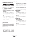
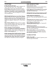
VANTAGE 500 CUMMINS
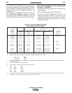
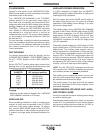
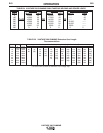
Table B.3 TYPICAL CURRENT RANGES
(1)
FOR TUNGSTEN ELECTRODES
(2)
DCEN (-) DCEP (+) Approximate Argon Gas Flow Rate
l/min (c.f.m.)
Tungsten
Electrode 1%, 2% 1%, 2% TIG TORCH
Diameter Thoriated Thoriated Aluminum Stainless Steel Nozzle
mm (in) Tungsten Tungsten Size (4), (5)
.25 (0.010) 2-15 (3) 2-4 (3-8) 2-4 (3-8) #4, #5, #6
.50 (0.020) 5-20 (3) 3-5 (5-10) 3-5 (5-10)
1.0 (0.040) 15-80 (3) 3-5 (5-10) 3-5 (5-10)
1.6 (1/16) 70-150 10-20 3-5 (5-10) 4-6 (9-13) #5, #6
2.4 (3/32) 150-250 15-30 6-8 (13-17) 5-7 (11-15) #6, #7, #8
3.2 (1/8) 250-400 25-40 7-11 (15-23) 5-7 (11-15)
4.0 (5/32) 400-500 40-55 10-12 (21-25) 6-8 (13-17) #8, #10
4.8 (3/16) 500-750 55-80 11-13 (23-27) 8-10 (18-22)
6.4 (1/4) 750-1000 80-125 13-15 (28-32) 11-13 (23-27)
(1) When used with argon gas. The current ranges shown must be reduced when using argon/helium or pure helium shielding gases.
(2) Tungsten electrodes are classified as follows by the American Welding Society (AWS):
Pure EWP
1% Thoriated EWTh-1
2% Thoriated EWTh-2
Though not yet recognized by the AWS, Ceriated Tungsten is now widely accepted as a substitute for 2% Thoriated Tungsten in AC
and DC applications.
(3) DCEP is not commonly used in these sizes.
(4) TIG torch nozzle “sizes” are in multiples of 1/16ths of an inch:
# 4 = 1/4 in. 6 mm
# 5 = 5/16 in. 8 mm
# 6 = 3/8 in. 10 mm
# 7 = 7/16 in. 11 mm
# 8 = 1/2 in. 12.5 mm
#10 = 5/8 in. 16 mm
(5) TIG torch nozzles are typically made from alumina ceramic. Special applications may require lava nozzles, which are less prone to
breakage, but cannot withstand high temperatures and high duty cycles.