


NOTE: DIAGRAMS & ILLUSTRATIONS NOT TO SCALE.
3
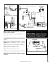
Step 10. Install the field-provided ON/OFF switch in a convenient
location on a wall, near the fireplace.
Step 11. Route a 3-wire, 120Vac power line to the ON/OFF switch as
shown in
Figure 9
(for Millivolt model) and
Figure 10
(for Electronic
model).
Then route the wires to the unit’s junction box. Remove the receptacle
box by squeezing the sides of the J-Box and slide the two tabs through
the cutout.
Step 12. Connect the supply wires to the receptacle as shown in
Figure 9
(for Millivolt) and
Figure 10
(for Electronic). Reinstall the
receptacle box.
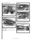
Step 13. Plug the blower cord into the receptacle (
see Figure 11
).
Step 14. Reinstall items from Steps 7, 6 and 5.
Step 15. Restore the electrical power to the unit.
Step 16. Start the fireplace by following the procedures indicated in
the lighting instructions section of the Homeowners Care And Opera-
tions instructions manual, supplied with the fireplace.
Step 17. Check the start-up and shutdown, and the running operation
of the blower.
Figure 9
Figure 10
JUNCTION BOX
W
GR
BK
120 VAC
BK
R
TRANSFORMER 3V
INTERMITTENT ELECTRONIC WIRING DIAGRAM
BROWN
BROWN
BLACK
BATTERY BACK-UP
TO WALL
SWITCH OR
THERMOSTAT
BLACK (SENSOR)
BLACK (IGNITOR)
SPARK TO PILOT IGNITOR
IGNITOR MODULE
3V
RED
BK
W
GR
OPTIONAL BLOWER
SWITCH
FAN
(OPTIONAL)
PILOT
IN
OUT
VENT
LO
HI
TH
TP
TH
TP
IN
ORANGE (THTP)
BLACK (TP)
GREEN (TH)
TP-TH
TP
TH
APPLIANCE- MOUNTED
ON/OFF SWITCH
BK/W(1)
BK/W(1)
WALL-MOUNTED ON/OFF SWITCH (OPTIONAL)
THERMOSTAT (OPTIONAL)
JUNCTION BOX
BLACK
W
GR
120 V
AC
WALL MOUNTED CONFIGURATION FOR FAN SWITCH (OPTIONAL)
BK
R
WIRING DIAGRAM MILLIVOLT GAS VALVES
THERMOPILE
GAS VALVE
FAN
(OPTIONAL)
IMPORTANT: Ground lead must be connected to the green screw
located on the junction box. Failure to do so will prevent the
appliance from operating. The appliance must be electrically
grounded in accordance with local codes or, in the absence of local
codes, the National Electrical Code, ANSI/NFPA 70-(latest edition).
(In Canada, the current CSA C22-1 Canadian Electrical Code.)
BLOWER MOUNTING TABS
BLOWER ASSEMBLY
ELECTRICAL OUTLET
Figure 11