


Lennox Hearth Products; 1110 West Taft Avenue; Orange, CA 92865 Part #775146M Rev. A, 12/03, Page 2 of 2
9. Connect the black wire from the blower
(step 6) to the black rheostat wire. Using a
¼” nut driver, install the rheostat housing
onto the rear shroud using the 2 screws
provided. Ensure that the wires and
connectors are completely through the
hole and contained in the rheostat
housing. See Figure 9.
10. Reinstall rear shroud (reverse step 3 on
page 1).
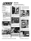
11. Reconnect the 2 black on/off switch
wires to the valve (TP/TH and TH
terminals). See Figure 1 and Figure 10.
Reconnect burner switch wires.
BLOWER OPERATION:
When the stove heats up, the blower will
automatically turn on at the speed determined
by the rheostat. To adjust the blower speed,
dial the rheostat to the desired speed setting.
Turn the knob clockwise just past the click
(the first ON position) for the highest speed
setting. Turning the knob further clockwise
will provide slower blower speeds. Note: If the
rheostat is not turned “on”, the blower will not
operate.
WARNING: The power cord MUST
BE PLUGGED DIRECTLY INTO A
PROPERLY GROUNDED, 120 VOLT,
60 HZ, 3-PRONG RECEPTACLE
electrical outlet. Do not cut or
remove the grounding prong from
this plug. It must be routed to avoid
contact. Do not route power cord
under or in front of appliance.
INSTALLATION INSTRUCTIONS:
(for units WITH a Full function flame
modulating Remote Control System, H0301
or H0302)
Note: The rheostat assembly, fan disc (with
wire) and the #8 screws will not be used.
1. Install the blower, disconnect the on/off
switch wires and remove the rear shroud
(Follow steps 1, 2 & 3 on page 1).
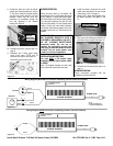
2. Connect the 2 black wires together from
the blower assembly. See Figure 11 and
14.
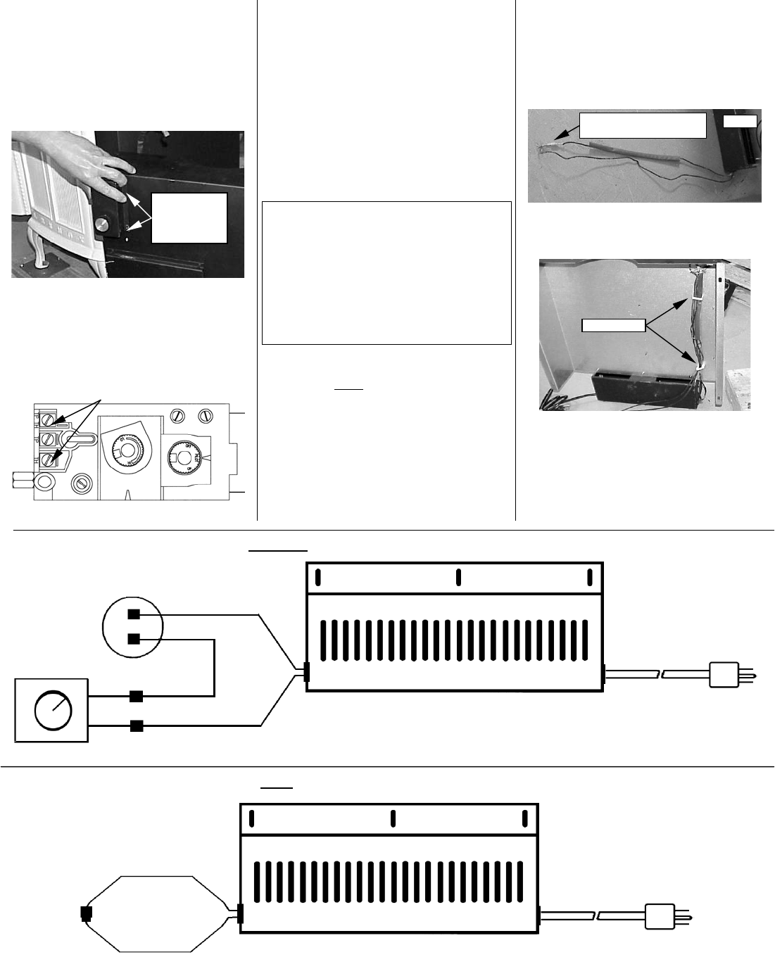
3. Stow wires into existing wire holders on
the inside of rear shroud. See Figure 12.
4. Reinstall rear shroud (reverse step 3 on
page 1).
BLOWER OPERATION:
Follow instructions provided with the
modulating remote control kit.
Wiring Diagram (WITHOUT full function modulating remote control kit installed)
BLOWER ASSEMBLY
POWER CORD
M
M
F
F
FAN DISC
RHEOSTAT
WHITE
NOTE:
M = MALE CONNECTOR
F = FEMALE CONNECTOR
BLOWER MOUNTING
BRACKET
WHITE
BLACK
BLACK
BLACK
BLACK
BLACK
M
F
POWER CORD
BLOWER ASSEMBLY
BLOWER MOUNTING
BRACKET
Fi
g
ure 9
Secure rheostat
housing to
shroud using 2
screws provided
Fi
g
ure 10
Connect the 2 black wires
together from blower.
Blowe
r
Fi
g
ure 11
Wiring Diagram (WITH full function modulating remote control kit installed)
Fi
g
ure 12
F
F
Fi
g
ure 13
Fi
g
ure 14
Wire Holder
s