


Rev. B 1/12
4
7050ES Rev. B 1/12
9 7050ES
misto
TM
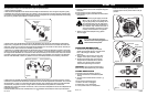
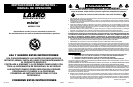
Outdoor Misting Fan: Misting Manifold Clean and Care Guide:
If the nozzles become clogged from contamination, follow the steps below:
1. Turn the water off at the source.
2. Remove the misting assembly’s valve adapter from garden hose or spigot and the hose adapter. Do this
carefully and allow residual water pressure to drain. Cycle (turn the handle back and forth) the valve and en-
sure freedom of movement and that there is no debris blocking the water’s path.
3. Remove the screen filter from inside the Misting Assembly Valve Adapter. Inspect and ensure the screen
filter is free of buildup or debris. If filter is clogged, soak in a solution of undiluted 5% acidity distilled white
vinegar for at least 2 hours. For an immediate solution, replace the filter.
4. Carefully remove each misting nozzle from the nozzle housing by turning it counter-clockwise using your
hand or, if required, a pair of pliers. Soak the nozzles in a solution of undiluted 5% acidity distilled white
vinegar for at least 2 hours. For an immediate solution, replace the nozzles with the supplied replacement
parts. If more nozzles are required, call 1-800-233-0268, or order online at www.laskoproducts.com in Parts &
Accessories.
5. After the appropriate amount of soak time for the parts requiring cleaning, reassemble the misting
subsystem by inserting the misting nozzles into the Nozzle Housing and turning clockwise until secure.
(Figure 5) Only turn until hand tight; do not over tighten. Next, return the screen filter to the inside of the
manifold’s valve adapter. Finally, reattach the valve adapter to the hose adapter. (Figure 4)
6. You are now ready to continue to stay cool with your misto
TM
Outdoor Misting Fan.
MODELO 7050
Misting
Assembly
Valve Adapter
Hose Adapter
Rubber Gasket
Misting Nozzles Nozzle Housing
Figure 4
Screen Filter
Figure 5
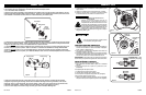
INSTRUCCIONES DE ENSAMBLAJE (Figura 1)
1. Cuidadosamente retire el ventilador de la bolsa plástica y de la
caja de cartón.
2. Coloque el ventilador sobre una superficie firme y nivelada.
3. Conecte el enchufe GFCI en una toma de corriente estándar
de corriente alterna de 120 voltios con conexión a tierra.
Asegúrese que el enchufe encaje firmemente en el
tomacorriente.
Cuando los enchufes quedan flojos en los
tomacorrientes, pueden deslizarse parcial o
completamente fuera del tomacorriente con un leve
movimiento del cable adosado. Los tomacorrientes
en este estado podrían sobrecalentarse y representar
un grave peligro de incendio; si está cubierto por una
cortina o tela, el riesgo de incendio es aún mayor.
4. Conecte el adaptador de la válvula de la manguera a cualquier
manguera de jardín o grifo.
Si usa un cable de extensión, se debe conectar
a un receptáculo protegido de GFCI.
INSTRUCCIONES DE OPERACION
1. Encienda el ventilador al seleccionar la velocidad deseada con
la Perilla de encendido en un lado del ventilador. 0-Apagado,
3-Alto, 2-Medio, 1-Bajo (Figura 2)
2. Abra el agua en la fuente. Gire el adaptador de la válvula a la
posición de "Abierto". (Figura 3)
3. Para ajustar el ángulo vertical, presione el cuerpo del ventilador
hacia adelante o hacia atrás a la posición deseada. Es normal
escuchar un sonido de clic mientras realiza esta función.
IMPORTANTE: El ángulo de rociado y el tamaño de la gota están
determinados por la presión del agua donde usted se encuentra.
OSCILACIÓN DE LA REJILLA:
Para operar el aire interno que dirige las rejillas:
1. Gire la Perilla de encendido hasta el ajuste de la velocidad
deseada.
2. Ponga el interruptor de la rejilla en la posición de "On"
(Encendido).
Las rejillas dejarán de operar cuando:
1. Se desconecta la corriente de la unidad.
2. La Perilla de encendido está en posición 0-Off.
3. El interruptor de la rejilla está en posición "Off" (Apagado).
Para centrar las rejillas en el flujo de aire:
1. Observe las rejillas durante la operación. Una vez centradas,
coloque el interruptor de la rejilla en la posición "Off" (Apagado).
Figura 1
Figura 2
Interruptor de
la rejilla
Perilla de
encendido
Adaptador de la
válvula de la manguera
Figura 3
MODEL 7050