


6
Section 1: Assembly & Set-Up
SP2060, SP2072, SP3072 & SP3084 Soil Pulverizers 307-099M
Table of Contents
7/11/12
Tractor Requirements
Tractor horsepower and hitch category should be within
the range noted below. Tractors outside the horsepower
range must not be used.
• SP20 Tractor Horsepower Rating25-35 HP
• SP30 Tractor Horsepower Rating 30-50 HP
• SP20 & SP30 Hitch CategoryCat. I
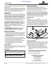
Dealer Preparations
!
CAUTION!
Never allow anyone under unit while unloading.
Using a lifting device of adequate size to remove crate
from flat bed. Place on a smooth flat work surface and
uncrate unit. This unit is shipped partially assembled. It is
the dealership’s responsibility to finish assembly of the
unit. This section covers the proper way for the Land
Pride dealer to assembly the pulverizer.
Assembly Instructions
Review all safety instructions printed in this manual
before assembling the pulverizer.
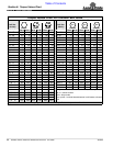
Torque Requirements
Refer to “Torque Values Chart” on page 14 to
determine correct torque values when tightening
hardware.
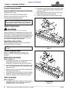
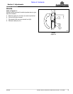
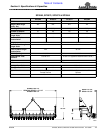
SP20 Hitch Assembly
Refer to Figure 1-1:
1. Install upper hitch plates (#1 & #2) inside mounting
bracket plates with 3/4"-10 x 2" GR5 cap
screws (#4), lockwashers (#8), and hex nuts (#6).
2. Insert spacer (#3) between upper hitch plates, install
3/4"-10 x 4" GR5 cap screw (#5), lockwashers (#8),
and hex nut (#6).
3. Make sure 3/4" hex jam nuts (#10) is screwed fully
onto lower hitch pins (#11).
4. Install lower 3-point hitch pins (#11) to the pulverizer
frame with 7/8" lock washers (#9) and hex nuts (#7).
5. Tighten all Hardware to the proper torque values.
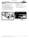
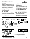
Hitch Assembly
Refer to Figure 1-2:
1. Install upper hitch plates (#2 & #3) inside mounting
brackets with 3/4"-10 x 2" GR5 cap screws (#5),
lockwashers (#8), and hex nuts (#7).
NOTE: Front tractor weights and/or ballast to tires
may be required to offset weight of unit. Consult your
tractor manual for details to install ballast weights.
NOTE: Do not tighten hardware until assembly is
complete.
Section 1: Assembly & Set-Up
2. Insert spacer (#4) between upper hitch plates. Install
3/4"-10 x 4" GR5 cap screw (#6), lockwasher (#8),
and hex nut (#7).
3. Insert lower 3-point hitch pins (#9) into clevis lugs.
Secure hitch pins with linch pins (#9).
4. Tighten all Hardware to the proper torque values.
Hitch Assembly
Figure 1-1
Hitch Assembly
Figure 1-2
30156
30157