


19
Section 3: Operating Instructions
2/02/09
RC5020 (540 RPM) and RCM5020 (1000 RPM) Rotary Cutters 318-474M
Land Pride
Table of Contents
Field Set-up
!
WARNING!
The following operational procedures should be carried out by
the tractor operator. Other persons should be cleared of the
area even during cutter set-up. Cutter operation should be
stopped when in the vicinity of other persons.
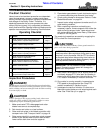
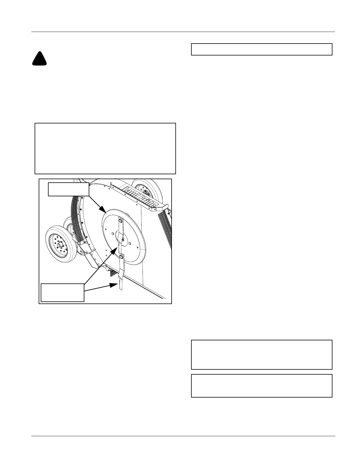
Refer to Figure 3-3:
1. Inspect wing blade carriers and cutting blades prior
to lowering the wings.
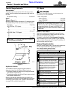
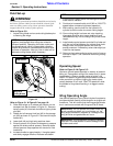
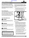
Wing Deck Blade Positioning
Figure 3-3
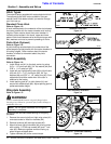
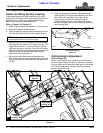
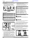
Refer to Figure 3-1 & Figure 3-2 on page 18:
2. Raise both wings up to release any tension on the
transport lock bar as shown in Figure 3-1. Remove
hairpin cotter (#1) from both the left and right cylinder
pins (#4).
3. Rotate end of transport lock bar (#3) to the storage
pin (#2) as shown in Figure 3-2. Secure with hairpin
cotters (#1).
4. Lower both left and right wing sections down.
5. Extend hydraulic lift cylinder to release any pressure
against the stroke control spacers. Remove stroke
control spacers. Keep spacers with tractor for field
installation.
6. Increase throttle to approximately 1/4 engine speed
and slowly engage driveline. Also see note below.
NOTE: The cutting blades may become locked
together (overlapped) when wings are raised to
transport position. Operating the cutter under such
circumstances will result in severe deck vibration.
Inspect wing decks for a locked blade condition prior
to power-on operation. Use a pry bar or other tool to
separate cutting blades when necessary.
24854
Wing Deck
Cutting Blades
Blade Carrier
7. Ensure that all power shafts are rotating and that the
cutter has no vibration.
8. Continue to increase throttle to full 540 or 1000 PTO
speed before commencing forward operation.
9. While cutting, use the lever for the hydraulic lift
cylinder to set the cutter to correct cutting height.
10. Once cutting height has been set, stop traveling,
disengage driveline, shut tractor engine off and
remove switch key. Do not change lift cylinder stroke
length.
11. Install stroke control spacers onto the lift cylinder rod
until the rod is filled between the cylinder and clevis.
Always install the largest spacers first and the
smaller ones last. If necessary, raise cutter slightly to
install the last spacer.
12. Return to the tractor and bring cutter up to full rpm as
outlined in steps 7,8&9andthen continuing cutting
operation.
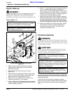
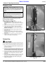
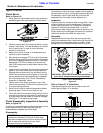
Operating Speed
Refer to Figure 3-4 & Figure 3-5:
Optimum ground speed depends on density of material
being cut, horsepower rating of the tractor and (in some
cases) terrain. Always operate tractor at cutter’s full
rated PTO speed in a gear range that allows the cutter to
make a smooth cut without lugging the tractor down,
usually between 2 to 5 mph. Low PTO speed will allow
the blades to hinge back resulting in a ragged uneven
cutting.
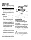
Wing Operating Angle
Use the float position of your tractor’s hydraulic system to
provide automatic floating of the wings for varying terrain
conditions. This will ensure that the wing gauge wheels
are in continuous contact with the ground at all times.
NOTE: Use tractor’s PTO soft start option if available.
IMPORTANT: Do not operate this cutter under any
terrain conditions where, on a continuous cut, the
wing angle exceeds 45 degrees up. Damage to the
wing driveline and gearboxes can occur.
IMPORTANT: During operation, the wing lift lever(s)
must be in the float position to avoid damage to the
cylinders and axles.