18
Section 3: Operating Instructions
RC5014 (540 RPM) and RCM5014 (1000 RPM) Rotary Cutters 330-117M 2/02/08
Land Pride
Table of Contents
Transport Locks
The cutter wing will need to be raised before transporting
on a roadway, through narrow gate openings and when
servicing the deck underside.
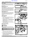
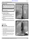
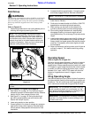
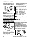
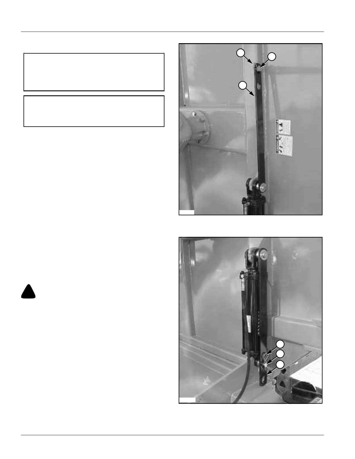
Refer to Figure 3-1 & Figure 3-2:
1. Disengage tractor PTO and wait for cutter blades to
come to a complete stop before raising cutter wing.
2. Raise cutter wing fully up with hydraulics.
3. Place tractor gear selector in park, shut tractor engine
off, remove switch key and dismount from tractor.
See Figure 3-1:
4. Remove hairpin clip (#1) from storage pin (#2).
Remove transport lock bar (#3) from storage position.
See Figure 3-2:
5. Swing transport lock bar (#3) to locked position and
place over lock pin (#4). Secure with hairpin clip (#1).
Transporting
!
CAUTION
When traveling on public roads at night or during the day, use
accessory lights and devices for adequate warning to operators
of other vehicles. Comply with all federal, state and local laws.
1. Select a safe ground speed when transporting from
one area to another.
2. Be sure to reduce tractor ground speed when turning
and leave enough clearance so the cutter does not
contact obstacles such as buildings, trees or fences.
3. Always raise the wing and set the transport lock to
keep wing decks from falling before traveling on
public roadways.
4. When traveling on roadways, transport in such a way
that faster moving vehicles may pass you safely.
5. Shift tractor to a lower gear when traveling over
rough or hilly terrain.
IMPORTANT: Always disengage tractor’s PTO and
wait for blades to stop before raising cutter wings to
transport position. Drivelines and gearboxes will be
damaged if cutter wings are raised while PTO is
turning.
NOTE: The wing is controlled with a hydraulic lift
cylinder. Be certain that the wing hydraulics are
attached to the tractor and the hydraulic hoses are full
of oil before proceeding.
Transport Bar, Storage Position
Figure 3-1
Transport Bar, Locked Position
Figure 3-2
23593
1
3
2
1
23592
4
3


