


17
Section 1: Assembly and Set-up
8/28/08
RC5010 & RC6010 (540 RPM) and RCM5010 & RCM6010 (1000 RPM) Rotary Cutters 318-128M
Land Pride
Table of Contents
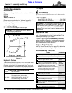
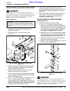
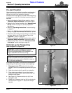
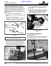
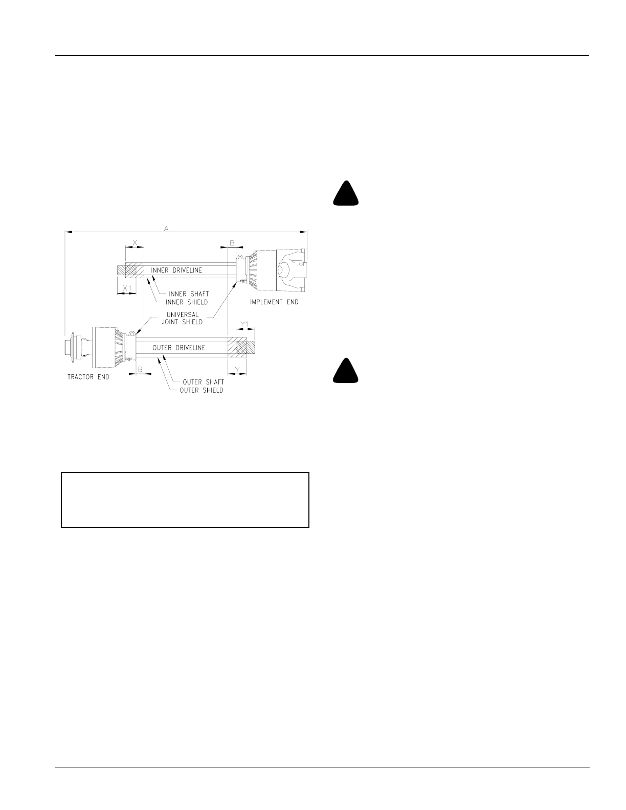
d. Cut off inner shield at the mark (“X” dimension).
Cut the same amount off the inner shaft (“X1”
dimension). Repeat cut off procedure (“Y”&“Y1”
dimensions) to the outer driveline half.
e. Remove all burrs and cuttings.
f. Apply multi-purpose grease to the inside of the
outer shaft and reassemble driveline.
g. Attach inner driveline yoke end to the divider
gearbox shaft.
h. Attach outer driveline yoke end to the tractor's
shaft.
PTO Driveline Shortening
Figure 1-11
4. The driveline should now be moved back and forth to
insure both ends are secured to the tractor and cutter
PTO shafts. Reattach any end that is loose.
5. Refer to Figure 1-10 on page 16. Secure chains (#6)
on driveline (#5) around hitch clevis rod to restrict
driveline outer shield from rotating. Re-latch safety
chain to driveline guard.
6. Attach safety chain located on the other end of the
driveline (#5) to the cutter’s main frame to restrict
driveline inner shield from rotating. Re-latch safety
chain to driveline guard.
Hydraulic Hook-up
Refer to Figure 1-10 on page 16:
The Rotary Cutter is equipped with two hydraulic
cylinders with one in the center for lifting the cutter and
one on the wing for folding the wing. Both cylinders on
the cutter are set-up for single action (one-way)
operation.
22165
IMPORTANT: Two small chains are supplied with
each driveline. These chains must be attached to
the outer and inner driveline shields and to the cutter
deck or hitch to restrict the shields from rotating.
Each duplex outlet on your tractor can perform only one
operation. One outlet is needed for lifting the cutter and
the other for lifting the wing.
Your Land Pride dealer can help you determine the best
configuration that will match your needs and your tractor
capabilities. Optional control valve kits are available if the
tractor does not have the required number of duplex
outlets. For additional information, See Hydraulic Outlets
on page 12
!
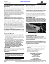
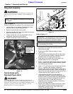
DANGER!
Hydraulic fluid under pressure can penetrate skin. Wear
protective gloves and safety glasses or goggles when working
with hydraulic systems. Use a piece of cardboard or wood
rather than hands when searching for hydraulic leaks. If
hydraulic fluid is injected into the skin, it must be treated by a
doctor within a few hours or gangrene may result.
1. Route cylinder hoses (#7) through hose support loop
and connect to tractor remote outlets.
2. Cycle hydraulic system by raising and lowering center
deck cylinder and wing fold cylinder. It may be
necessary to purge thehydraulicsystem of trapped air
if operation is sluggish.
!
WARNING!
Be sure center deck and wings are lowered to the ground and all
hydraulic pressure is relieved before disconnecting any
hydraulic lines or fittings between the Rotary Cutter and tractor
hydraulic system.
The hydraulic system may be purged as follows:
a. With wing lowered to the ground, loosen hydraulic
hose fitting at wing cylinder slightly to allow fluid to
escape.
b. Slowly activate tractor control valve to purge any
trapped air from the system.
c. Tighten each fitting.
3. The center deck lift cylinder is purged in the same
manner as the wing cylinder. The lift cylinder must be
fully retracted and the cutter resting on the ground
before loosening hose fitting as described in 2a
above.
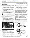
4. Check driveline for adequate clearance under all
ranges of cutter height. With driveline shaft attached
to the tractor, slowly raise and lower cutter to its
upper and lower limits while observing clearances
between hitch and driveline. Adjust tractor drawbar
height and/or length if driveline interferes. See
Figure 1-1 on page 12 for correct drawbar
dimensions.