TP-6804 1/1556 Section 4 DC2 Controller Operation
4.2.1 Controller Keypad
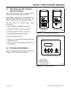
The RUN, OFF, and AUTO buttons control the
generator set as described in Figure 4-3.
Use the EXERCISE button to set the exerciser on the
DC2 controller. See Section 4.5 for instructions to set
the exerciser.
Note: A personal computer (laptop) with Kohlerr
SiteTecht software is required for changing
settings on the DC2 controller.
4.2.2 LED Indicators
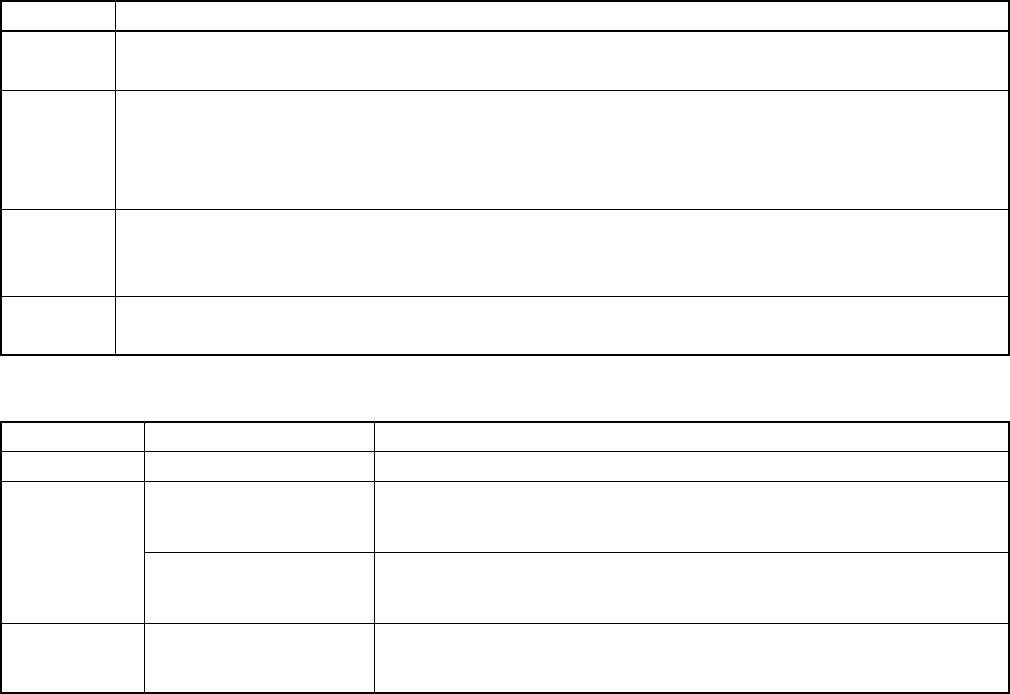
LEDs above the RUN, OFF, and AUTO buttons indicate
the mode of operation as shown in Figure 4-4.
Button Button Function
RUN Press to start the generator set. The engine start time delay is ignored.
The software version and engine model are displayed briefly when RUN is pressed.
OFF Stops the generator set. The cooldown time delay is ignored.
During the engine crank cycle, pressing OFF will stop the c rank cycle.
Press to clear faults and reset the controller.
Press and hold to access the event log.
AUTO Press to place the generator set in A utomatic (standby) mode.
Press to exit the event log.
Press and hold AUTO and OFF to reset the maintenance timer.
EXERCISE When the c ontroller is in AUTO mode, press to set the exerciser. See Section 4.5.
When the controller is OFF, press and hold to reset the OnCuer password. See Section 4.8.
Figure 4-3 DC2 Controller Pushbutton Operation
LED LED Indication Description
RUN RUN LED is on. Generator set is running. Remote start and stop commands are ignored.
OFF
OFF LED lights for 2
seconds, then flashes
every 2 seconds.
Generator set and controller are off. Remote start/stop commands have no
effect. The exercise cycle will not run.
In Auto mode, OFF LED
flashes quickly to indicate
a fault shutdown.
Attention required. Identify and correct the fault condition before resetting the
controller.
AUTO AUTO LED is on. Automatic (standby) mode. Generator set will respond to engine start and
stop commands from the controller (for example, exercise start and stop
commands) or an ATS. Time delays operate as described in Section 2.3.
Figure 4-4 DC2 Controller LED Operation


