


23
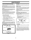
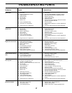
TO REMOVE WHEEL FOR REPAIRS
(See Fig. 28)
• Block up axle securely.
• Remove axle cover, retaining ring and washers to allow
wheel removal (rear wheel contains a square key - Do
not lose).
• Repair tire and reassemble.
• On rear wheels only: align grooves in rear wheel hub
and axle. Insert square key.
• Replace washers and snap retaining ring securely in
axle groove.
• Replace axle cover.
NOTE: To seal tire punctures and prevent fl at tires due to
slow leaks, tire sealant may be purchased from your local
parts dealer. Tire sealant also prevents tire dry rot and
corrosion.
TRANSMISSION REMOVAL/RE PLACE MENT
Should your transmission require removal for service or
replacement, it should be purged after reinstallation and
before operating the tractor. See “PURGE TRANS MIS SION”
in the Operation section of this manual.
SERVICE AND ADJUSTMENTS
TO AD JUST STEER ING WHEEL ALIGN-
MENT
If steering wheel crossbars are not horizontal (left to right)
when wheels are positioned straight forward, remove steer-
ing wheel and reassemble per instructions in the Assembly
section of this manual.
FRONT WHEEL TOE-IN/CAMBER
The front wheel toe-in and camber are not adjustable on
your tractor. If damage has occurred to affect the front
wheel toe-in or camber, contact your nearest authorized
service center/department.
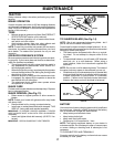
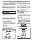
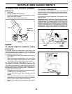
CLUTCH LOCATOR
STA TION ARY
IDLER
CLUTCH ING
IDLER
ELECTRIC
CLUTCH
FIG. 26
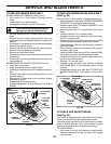
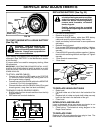
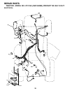
TO REPLACE MOTION DRIVE BELT
(See Fig. 27)
Park the tractor on level surface. Engage parking brake.
For assistance, there is a belt installation guide decal on
bottom side of left footrest.
• Remove mower (See “TO REMOVE MOWER” in this
section of this manual.)
• Disconnect clutch wire harness.
• Remove clutch locator.
• Remove belt from stationary idler and clutching idler.
• Pull belt slack toward rear of tractor. Carefully remove
belt upwards from transmission input pulley and over
cooling fan blades.
• Pull belt toward front of tractor and remove down wards
from around electric clutch.
• Install new belt by reversing above procedure.
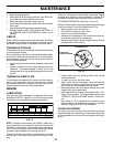
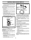
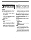
WITH PARKING BRAKE “ENGAGED”
JAM NUT
DO NOT TOUCH THIS NUT. IF FURTHER BRAKE AD JUST MENT
IS NECESSARY CONTACT YOUR NEAR EST AUTHORIZED SER-
VICE CENTER/DEPARTMENT
OPERATING
ARM
NUT “A”
1-3/4"
• Disengage transmission by placing freewheel control
in “transmission disengaged” position. Pull freewheel
con trol out and into the slot and release so it is held in
the disengaged position.
The rear wheels must lock and skid when you try to manually
push the tractor forward. If the rear wheels rotate, the brake
needs to be adjusted or the pads need to be replaced.
TO ADJUST BRAKE
• Depress brake pedal all the way down and en gage
parking brake.
• Measure distance between brake operating arm and
nut “A” on brake rod.
• If distance is other than 1-3/4", loosen jam nut and turn
nut “A” until distance becomes 1-3/4". Retighten jam
nut against nut “A”.
• Engage transmission by placing freewheel control in
“trans mis sion engaged” position.
• Road test tractor for proper stopping distance as stated
above. Readjust if nec es sary. If stopping distance is
still greater than fi ve (5) feet in high est gear, further
main te nance is nec es sary. Replace brake pads or
contact a qualifi ed service center.
FIG. 27
CLUTCH
WIRE HAR NESS
TRANS MIS SION
INPUT PULLEY