


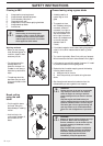

18 – English
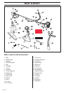
ASSEMBLY
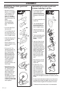
Assembling the blade guard and
clearing blade
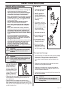
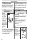
• Remove the mounting
plate (H). Fit the adapter
(I) and bracket (J) with
the two screws (K) as
shown. Fit the blade
guard (A) to the adapter
using the 4 screws (L) as
shown.
NOTE! Use the
recommended blade
guard. “See Technical
data“.
• Fit the drive disc (B) on
the output axle.
• Turn the blade axle until
one of the holes in the
drive disc aligns with the
hole in the gear housing.
• Insert the locking pin (C)
in the hole so that the
axle is locked.
• Place the blade (D) and
support flange (F) on the
output axle.
• Fit the nut (G). The
tightening torque of the
nut is 35-50 Nm (3.5 - 5
kpm). Use the socket
spanner in the tool kit.
Hold the handle of the
spanner as close to the
blade guard as possible.
The nut is tightened
when the spanner is
turned against the
direction of rotation (left-
hand thread).
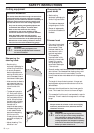
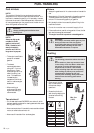
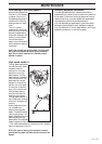
• When slacking off and
tightening the saw blade
nut, the hands may be
injured by the blade
teeth. Always hold your
hand protected by the
blade guard. This is
facilitated by the use of a
long box spanner. The
illustration shows the area
in which you should keep
the box spanner.
F
D
B
C
G
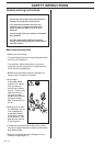
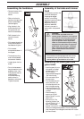
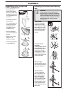
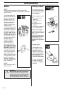
Assembling the spray guard and
trimmer head Tap´n´go Pro
K
J
I
G
F
I
A
K
B
C
trimmer guard as possible. The nut is tightened when the
spanner is turned against the direction of rotation (left-hand
thread).
• Fit the trimmer head‘s bottom section (K) on the cover (I)
by pressing the two sections together with the cut-outs on
the bottom section aligned with the catches on the cover.
• To dismantle follow the instructions in the reverse order.
• Fit the appropriate guard
(A) for use with the
trimmer head. Hook the
guard onto the shaft fitting
and secure it with the bolt
(L).
• Fit the drive disc (B) on the
output axle.
• Turn the blade axle until
one of the holes in the
drive disc aligns with the
hole in the gear housing.
• Insert the locking pin (C)
in the hole so that the axle
is locked.
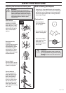
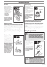
• The trimmer head must be
split to be fitted (see the
diagram). Proceed as
follows:
• Insert your finger into the
centre hole of the cover (I)
at the same time as you
hold the cover with your
other fingers. Press the two
catches (J) that extend from
the cut-out on the bottom
section (K) using the
thumb and index finger of
your other hand. Press
apart the trimmer head
using the fingers on the
cover.
• Place the cover (I) and the
support flange (F) on the
output axle.
• Fit the nut (G). The
tightening torque of the
nut is 35-50 Nm (3,5-5
kpm). Use the socket
spanner in the tool kit.
Hold the handle of the
spanner as close to the