


Operation 11
5WPMAN0705 (Rev. 5/9/2008)
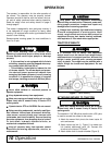
4. Adjust the tractor lower 3-point arm anti-sway
devices to prevent mower from swinging side to
side during transport.
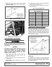
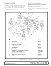
Figure 2. Attachment Points
Figure 3. Attaching Mower to Tractor
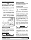
CUTTING HEIGHT ADJUSTMENT
Keep all persons away from operator control
area while performing adjustments, service, or
maintenance.
NOTICE
■ Avoid low cutting heights. Striking the ground
with blades produces one of the most damaging
shock loads a mower can encounter. Allowing
blades to contact ground repeatedly will cause
damage to mower and drive.
1. Level mower from side to side. Check by
measuring distance from mower frame to the
ground at each deck rail.
2. Verify that the same amount of spacers are under
all caster arms.
3. Control cutting height by adjusting front and rear
caster wheels.
4. To raise rear of mower, move caster adjustment
spacers under rear caster arms.
5. To raise front of mower, move spacers under front
caster wheel arms.
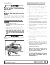
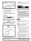
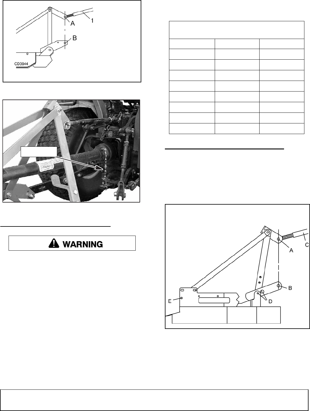
TRACTOR TOP LINK ADJUSTMENT
When the cutting height is set, adjust tractor top link
until mower top link attachment point (A), Figure 4, is
aligned vertically with mower hitch pin (B). The front
tires of the mower will lift off the ground before the rear
tires when the unit is raised. This will allow the mower
to follow the ground contour.
Figure 4. Top Link Adjustment
GM3054 Only
The GM3054 has two mower hitch plate attachment
points (D). It may be necessary to change the mower
hitch plate attachment point to obtain proper tire clear-
ance and/or lift height.
1. Tractor Top Link
A. Mower Top Link
Attachment Point
B. Mower Hitch Pin
CM906
Tether Chain
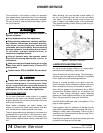
Table 1: Cutting Height Chart
Spacers Required Under
Caster Arm Pivot Tube
Cut Height 1/2" Spacer 1" Spacer
1" 00
1-1/2" 10
2" 01
2-1/2" 11
3" 02
3-1/2" 12
4" 03
4-1/2" 13
A. Mower top link attachment point
B. Mower hitch pin
C. Tractor top link
D. Mower hitch plate
attachment point
(GM3054 only)
(Rev. 6/1/2008)