


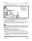
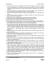
5. Attach the floating top link to the top hitch arms using the M16x90 bolt and stover
nut.
6. Attach the A-frame support to the floating top link using the M16x110 bolt with stover
nut.
7. Install the M20x110 bolt with the 1-1/8” spacer into the A-frame support.
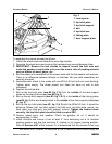
8. Insert the M20x140 bolt into the floating yokes. The order should be as follows: bolt,
first half of floating yoke, 1-3/8” bushing, A-frame support, M20 jam nut, second half
of floating yoke, M20 stover nut. The two M20 jam nuts need to be jammed against
each side of the linking plates of the grooming mower. This will allow some motion in
the bushing.
9. Loosen the M16x40 bolts that secure the top hitch arms to the rear support plates of
the mower. Only loosen slightly. The arms must be able to move slightly up and
down.
10.Tighten all hardware, ensuring all bolts and nuts have enough play to allow quick
hitch adapter to move up and down.
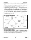
iMatch/Quick Hitch adapter operation:
After completing assembly of the adapter, the tractor lift arms should be raised and
locked in a position so the floating yokes are horizontal. Ensure that the M16x60 bolt is
approximately in the center of the slot on the floating yoke. Positioning the bolt in this
location allows the mower to have maximum float both up and down.
GROOMING MOWERS OPERATOR’S MANUAL
GENERAL INFORMATION 8 FRONTIER
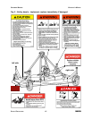
Fig. 4 - Quick-Hitch Adapter assembly.