


OPERATING INSTRUCTIONS
15
3. With BURST ON/OFF switch in OFF position, apply a
TTL gating signal of the proper width to the front panel
BURST INPUT jack.
Considerations
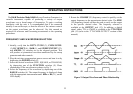
l. Make sure the tone burst and entire off period is viewed
when setting the repetition rate. The visible portion of the
off period could be incorrectly interpreted as the entire off
period. To avoid this error, use a low sweep speed on the
oscilloscope, adjusted to view the tone burst, off period,
and the beginning of a second tone burst.
2. The BURST WIDTH control does not interact with the
SWEEP TIME control and will not affect the repetition
rate. However, both controls affect the tone burst width.
Since the BURST WIDTH control adjusts the duty cycle
(percentage of repetition rate cycle in which tone burst is
produced), any subsequent adjustment of the SWEEP
TIME control affects the tone burst width, as well as the
off period. When setting the tone burst width to a specific
time period, adjust the SWEEP TIME control first, then
the BURST WIDTH control.
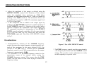
3. The tone burst output signal is always in full cycles or half
cycles. Note that as the BURST WIDTH control is adjusted
slowly, the tone burst is increased or decreased on half
cycle increments. This allows synchronization of the
waveform for oscilloscope viewing and eliminates
transients and frequency components not harmonically
related to the frequency being gated. This feature is
applicable to internal or external tone burst operation.
A
M OPERATION
The output of Model 4040A can be amplitude-modulated,
either by the internal 1 kHz signal, or by an external signal
applied to the VCG/MOD INPUT jack.
Internal
1. Set the carrier frequency using the main FREQUENCY
controls and RANGE switches.
2. Engage the MODULATION ON and AM
MODULATION switches.
3. Engage the INT MODULATION switch.
4. Set the percent of modulation by rotating the %
MODULATION control. Modulation can be set in
excess of 100%.
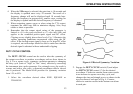
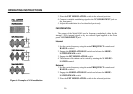
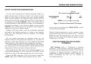
Fig. 6 shows the appearance of a carrier modulated by a
sine wave, and the quantities A and B which are used in
measuring percentage of modulation. The formula is:
Percent modulation = 2B/A x 100
Where A = unmodulated carrier level
B = modulation depth
External
l. Set the carrier frequency using the main FREQUENCY
controls and RANGE switches.
2. Engage the MODULATION ON and AM
MODULATION switches.