REV101805
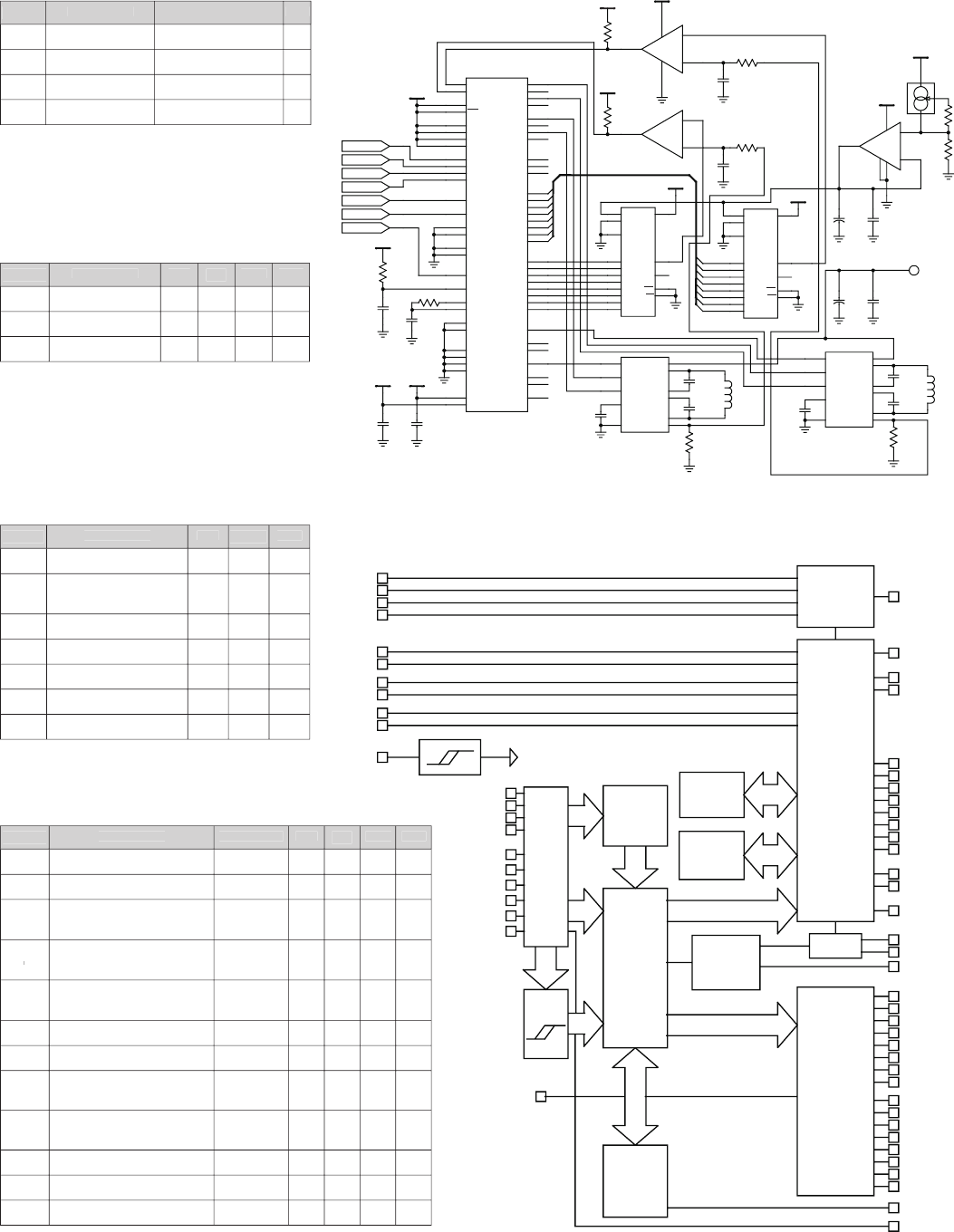
TYPICAL APPLICATION
48V, 3 Amps (RMS)/Phase Microstepping Driver
IM2000S ABSOLUTE
MAXIMUM RATINGS
RECOMMENDED
OPERATING CONDITIONS
ELECTRICAL
CHARACTERISTICS
AC Electrical Characteristics
BLOCK DIAGRAM
+5V
36
11
VSA
VSB
1
MODE
64
WR
OVCA
OVCB
37
10
24
OVV
26
OVTMPRES SEL 0
RES SEL 1
RES SEL 2
RES SEL 3
MSEL0
MSEL1
MSEL2
MSEL3
48
49
50
51
STEP CLOCK
DIRECTION
ENABLE
SCLK
DIR
EN
59
60
61
+5V
51K
55
56
CIR0
CIR1
RSEL
CSEL
52
53
0.47µf
30.1K
1.0nf
RESET
OSCR
OSCRC
57
23
22
IHI
ILOW
GND
GND
GND
GND
47
46
7
21
40
54
+5V
+5V
0.1µf
0.1µf
VCC
VCC
25
58
IM2000S
HLA
LLA
HRA
LRA
38
39
41
42
HLB
LLB
HRB
LRB
5
6
9
8
CURRED
FAULT
FSTEP
20
63
62
28
29
30
31
32
33
34
35
SINE0
SINE1
SINE2
SINE3
SINE4
SINE5
SINE6
SINE7
12
13
14
15
16
17
18
19
COS0/AD0
COS1/AD1
COS2/AD2
COS3/AD3
COS4/AD4
COS5/AD5
COS6/AD6
COS7/AD7
ENA
SIGNA
PWMA
43
44
45
ENB
SIGNB
PWMB
4
3
2
COUT
27
+5V
+5V
1K
1
8
3
2
+
-
4
TLC372
+5V
1K
7
5
6
+
-
TLC372
5.1K
220pf
5.1K
220pf
1
1
2
2
3
3
OUT1
OUT1
OUT2
OUT2
GND
GND
VDD
VDD
+5V
+5V
11
11
10
10
9
9
8
8
7
7
6
6
5
5
4
4
15
15
16
16
13
13
12
12
REF
REF
RFB
RFB
DB0
DB1
DB1
DB2
DB2
DB3
DB3
DB4
DB4
DB5
DB5
DB6
DB6
DB7
DB7
TLC524
TLC524
11
5
7
9
6
0.22µf
EN
IN1
IN2
VREF
GND
WR
WR
CS
CS
V+
OUT1
BOOT1
BOOT2
OUT2
VSEN
L6203
2
3
4
8
1
10
10nf
10nf
0.5
2W
ØB
+5V
LM234Z
68.1
R1
+5V
TLC271
6
7
3
2
4
8
0.1µf
10µf
+
+
-
0.22µf
L6203
0.5
2W
10nf
10nf
ØA
2
3
4
8
1
10
0.1µf
1000µf
+12 to +48V
+
EN
IN1
IN2
VREF
GND
V+
OUT1
BOOT1
BOOT2
OUT2
VSEN
11
5
7
9
6
DB0
DC Electrical Characteristics
V
DD
= +5.0 ±10%
T
OPR
= 25° C
Output Current (AMPS) = 0.002 x R1 (OHMS)
NOTE: Diodes may be needed on phase outputs depending on input voltage and phase currents used.
Symbol
Parameter
Limits
Unit
V
DD
DC Supply Voltage
V
SS
- 0.3 to +7.0
V
V
IN
Input Voltage
V
SS
-
0.3
to V
DD
+ 0.3
V
V
OUT
Output Voltage
V
SS
-
0.3
to V
DD
+
0.3
V
T
STG
Storage Temp
- 65 to +150
°C
Symbol
Parameter
Min
Typ
Max
Unit
V
DD
DC Supply Voltage
4.5
5.0
5.5
V
V
IN
Input Voltage
V
SS
—
V
DD
V
T
OPR
Operating Temp
- 20
—
85
°C
Symbol
Parameter
Min
Typical
Unit
t
RW
RESET pulse width
200
—
nS
t
S
MSEL, SCLK setup
time
—
100
nS
t
SW
SCLK pulse width
—
10
nS
t
WR
WR pulse width
—
20
nS
t
WH
Data hold time after
WR
0
—
nS
f
PWM
PWM chopping frequency
—
20
KHz
f
CLK
SCLK input frequency
—
10
MHz
Symbol
Parameter
Conditions
Min
Typ
Max
Unit
V
IL
Low level input voltage
—
—
—
0.8
V
V
IH
High level input voltage
—
2.0
—
—
V
V
T+
V
T+
V
Schmitt trigger positive
going threshold voltage
V
DD
= 5.0
—
3.0
—
V
V
T–
V
T–
V
Schmitt trigger negative
going threshold voltage
V
DD
= 5.0
0.6
—
—
V
V
H
Schmitt trigger hysteresis
voltage
V
DD
= 5.0
0.1
—
—
V
I
IL
Low level input current
V
IN
= V
SS
—
—
1.0
mA
I
IH
High level input current
V
IN
= V
DD
—
—
1.0
mA
V
OL
Low level output voltage
—
—
—
V
SS
+ 0.4
V
V
OH
High level output voltage
—
V
DD
- 0.4
—
—
V
I
OL
Low level output current
—
—
—
- 6.0
mA
I
OH
High level output current
—
—
—
3.0
mA
I
CC
Supply current
—
—
—
30
mA


