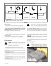
5. With the deck clutch switch up and/or the control levers in the
neutral position, slowly raise off of the seat. The engine should
stop.
6. If the engine fails to stop when the deck clutch switch is up or one
or both of the control levers is up and the operator is off the seat,
check the function of the seat switch. If the seat switch is not
operating properly (is not opening or closing) and if the cause can
not be determined, replace the seat switch.
If the problem can not be located, contact your Hustler Dealer.
WARNING: The safety interlock system should always
function per steps 4 and 5. If it does not function properly, it
should be corrected immediately. Do not operate machine
without properly functioning seat safety switch.
Engine starting
The tractor’s safety start interlock system is also designed to protect the
operator and others from accidental injury due to unintentional engine
starting. The engine starting motor will not engage until:
A. Control levers are in the park brake position.
B. Deck clutch switch is in the down (OFF) position.
WARNING: The safety interlock system must not be
disconnected or bypassed. Doing so could cause the machine
to operate unexpectedly resulting in personal injury.
NOTE: The operator’s seat is equipped with a separate safety switch.
If for any reason the operator should become unseated when the control
levers are not in the park brake position (park brake switches are
disengaged) or the deck clutch switch is engaged the engine will stop.
The following steps are the correct procedures for starting the engine.
If difficulty is encountered, contact the Hustler Dealer in your area.
1. Before starting tractor each day, perform daily pre-operation
checking. (See Safety start interlock system section)
2. Make sure the control levers are in the park brake position and deck
clutch switch is disengaged. Only start the engine from the
operator’s position.
3. Use choke, if unit is equipped with one, when engine is cold, or if
warm engine fails to start within 5 seconds of cranking. Avoid
flooding and operate engine without choking as soon as possible.
4. Set throttle at approximately 1/2 open position.
5. Insert key in ignition switch and rotate full clockwise to engage
starting motor. Release key when engine starts.
IMPORTANT: The engine starter should not be operated for periods
longer than 30 seconds at a time. An interval of at least two minutes should
be allowed between such cranking periods to protect the starter from
overheating and burn-out.
6. Perform test to make sure safety start interlock system is operating
properly. Refer to Safety start interlock system section.
7. As soon as engine begins to run, check to make certain the oil
warning light, check engine light and alternator warning light (if
applicable) are off. If not, stop engine immediately and check for
the cause.
8. Allow the engine to idle a few minutes before advancing the throttle
and/or engaging the deck clutch.
Stopping the engine
Use the following procedure to shut off the engine after operating the
equipment.
1. Place the control levers in the park brake position
2. Disengage the deck clutch
3. Throttle back to low idle for a couple of minutes
4. Rotate ignition key counter-clockwise to the OFF position. Remove
the key from switch before leaving the tractor.
Moving tractor with stalled engine
If it becomes necessary to move the tractor when the engine is
inoperative, the transaxles are equipped with bypass valves.
WARNING: Allow engine exhaust manifold to cool before
engaging or disengaging the bypass valves. The bypass
valve rods are located close to the exhaust system.
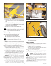
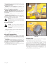
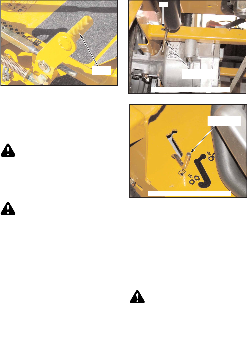
Mini Z 36/42 units produced prior to and including serial number
06120544 - Before moving the unit, pull out on the bypass valve rods and
slide them into the slot to lock in position.
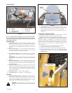
Both bypass valve rods are located underneath the rear of the tractor at
the back of the transaxle. Fig. 3-5A
The control levers must be placed in the neutral position, to release the
park brakes, so that the tractor can be moved.
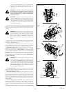
Figure 3-4
Deck lift
pedal
Figure 3-5B
Bypass valve rod
(Left rod shown)
Bypass valve rod shown in towing position
14
107708_0808
Figure 3-5A
Slot
Bypass valve rod
(Left rod shown)
(viewed from the rear left underneath side)


