


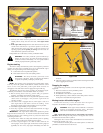

B. Deck lift pedal (Fig. 3-4) — the deck lift pedal is used to raise or
lower the deck. Push on the pedal to raise the deck and then place
the deck height locking pin into the desired cutting height hole.
Push the deck lift pedal to raise the deck when going over
obstructions.
Safety start interlock system
The tractor is equipped with a safety start interlock system consisting
of the park brake switches, seat switch, and deck clutch switch.
Check tractor safety start interlock system daily, prior to
operation. This system is an important tractor safety feature. It should be
repaired immediately if it malfunctions. The machine incorporates a
separate seat switch which will stop the tractor engine when the operator is
unseated for any reason while the tractor is operating. This is a safety
feature designed to prevent runaway or accidental entanglement. To
inspect the system:
1. The operator must be on the seat when testing the seat switch.
2. Set both control levers in the park brake position.
3. Start the engine and allow it to warm up to operating temperature.
4. With the deck clutch switch down and the control levers in the park
brake position, slowly raise off of the seat. The engine should
continue to run.
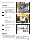
IMPORTANT: When access is required under the seat platform and
the seat is equipped with the optional arm rests, make certain to place
the control arms in the park brake position and pivot the arm rests
upward before placing the seat platform in the full forward position to
prevent arm rest damage.
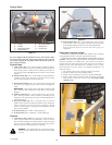
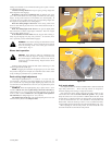
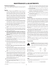
Control Panel
A. Choke control (Fig. 3-1) – a cable is linked to manually operate the
engine choke. When the lever is in the down position, the choke is
in the off (run) position. When the lever is pulled up, the choke is in
the on (start) position. Do not operate the machine in the on (start)
position.
B. Throttle control (Fig. 3-1) — a cable is linked to engine throttle for
controlling engine speed. Move lever forward to increase engine
rpm, move lever rearward to decrease engine rpm.
C. Deck clutch switch (Fig. 3-1) — this switch engages the deck. Pull
the switch up to engage and push switch down to disengage the
clutch.
IMPORTANT: Never engage clutch with engine running at high
rpm or when the deck is under load. Clutch, belts or deck could be
damaged.
D. Ignition switch (Fig. 3-1) – a three position switch: off, run, and
start. With key inserted, rotate it clockwise to START position;
release key when engine starts, and switch will automatically return
to the RUN position.
E. Oil pressure light (Fig. 3-1) — this light comes on when the
ignition switch is placed in the RUN position and stays lit until the
engine is running and a safe oil pressure is developed. If light
comes on during operation, shut engine off immediately and locate
and correct the problem.
F. 20 amp fuse (Fig. 3-1) — Main - 20 amp, blade-type
G. 10 amp fuse (Fig. 3-1) — Clutch/Aux - 10 amp, blade-type
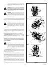
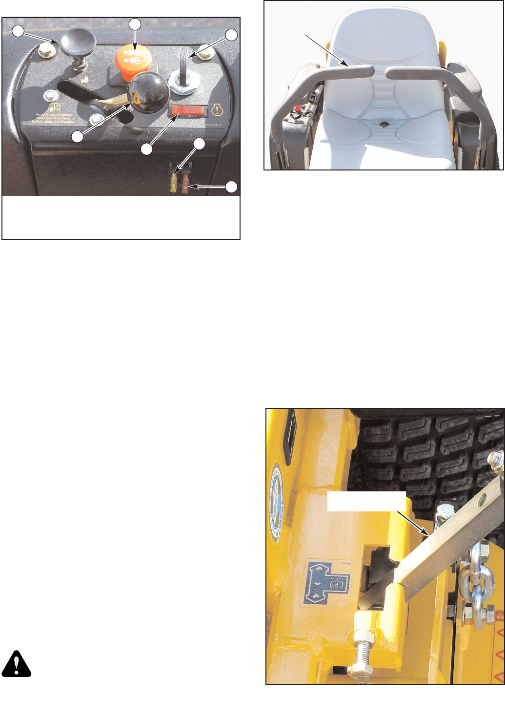
Controls
A. Control levers (Fig. 3-2 & 3-3) — these levers control the tractor’s
speed, direction, neutral lock, and park brake. Levers are used to
steer, accelerate, decelerate and change direction. When the control
levers are in the park brake position (3-3) the tractor will not move
when the engine is on and drive pumps are operating.
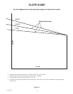
WARNING: The parking brake may not hold the tractor if
parked on a slope. Block or chock the machine when parked
on a slope
Figure 3-1
B
C
D
Figure 3-2
Control
lever
Shown with control levers
in neutral position
Control Panel
F
G
A - Choke E - Oil pressure light
B - Throttle F - 20 amp fuse
C - Deck clutch switch G - 10 amp fuse
D - Ignition switch
A
E
Figure 3-3
Control lever in park
brake position
13
107708_0808