


601156_0308 23
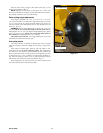
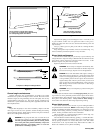
Lay the blade on a flat surface and check for distortion (Fig. 4-7 and 4-
8). Replace any distorted blade.
Do not re-use spindle bolts which have stripped, worn or undercut
threads. Torque bolts on spindles to 118 foot-pounds (160.01nm) when rein-
stalling blades.
IMPORTANT: The blade sail (curved part) must be pointing upward
toward the inside of the deck to ensure proper cutting.
IMPORTANT: When mounting blades, rotate them after installation to
ensure blade tips do not touch each other or sides of the mower.
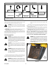
WARNING: Failure to correctly torque the bolt may result in
the loss of the blade which can cause serious injury.
WARNING: Mower blades are sharp and can cut. Wrap the
blade(s) or wear gloves and use extra caution when servicing
them.
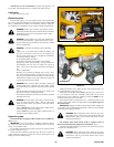
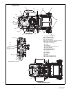
Seat adjustment
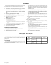
FasTrak 36/42 (Mini FasTrak 36/42) - The seat can be adjusted for-
ward and rearward by removing the locknut that locks the seat platform in
place and pivoting the seat platform up and forward. Then loosen the four
cap screws on the underneath side of the operator’s platform. Position the
seat where you have the best control of the machine and are the most com-
fortable and then tighten the cap screws. Fig. 4-9
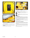
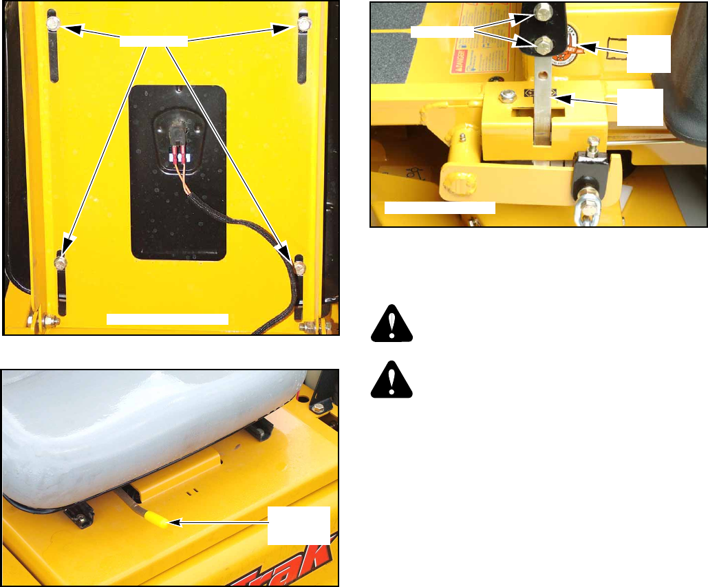
FasTrak 48/54 - The seat can be adjusted forward and rearward by slid-
ing the seat release handle and moving the seat until a comfortable operating
position is attained. Fig. 4-10
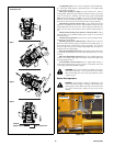
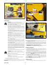
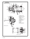
Steering control lever adjustment
The steering control levers can be adjusted for operator comfort. By
loosening the cap screws that attaches the upper control lever to the lower
lever (Fig. 4-11), the upper control lever can be pivoted to fit the operator’s
personal preference.
The steering control levers can also be adjusted up and down. Remove
the cap screws and slide the upper control lever up or down and align the
holes in it with the holes in lower lever. Re-install the cap screws and
tighten.
The steering control levers should be adjusted so that they align with
each other when in the neutral position.
Figure 5-11
Upper
control
lever
Lower
control
lever
FasTrak 36/42 shown
Cap screw
Figure 5-1
FasTrak 36/42 shown
Cap screw
Figure 5-10
Figure 5-9
Seat
release
handle