9-24 110907 01/09
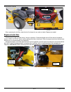
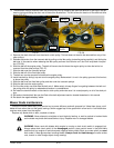
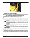
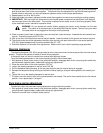
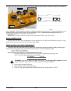
5. Both steering control levers need to be in the brake position when starting the engine, but need to quickly be
moved out of the brake position once engine is started so the brakes do not fight the transmissions since they have
not yet been adjusted.
6. Start the engine. Move the control lever to just engage the brake (neutral) slot and hold it in that position (Do not
engage the control lever far enough to engage the brakes in the brake slot) (FIG. 36).
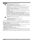
WARNING: This operation is extremely dangerous. Pay close attention when adjusting the
transaxle control rod so you do not get your fingers, tools, or anything else close to the EZT
transaxle’s cooling fans.
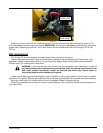
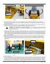
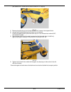
7. Beginning with the RH side of the tractor, adjust the steering control rod so that the RH drive axle just starts turning
in the forward rotation while the steering lever remains in the neutral positon. Now, turn the steering rod back the
opposite direction to the point when the drive axle stops spinning. From that point, turn the steering rod back again
½ turn. This ensures that the steering rod is adjusted so that the transmission control arm is centered in the neutral
band of the transmission.
8. Move the lever forward and backward and make sure that the drive axle spins forward and backward correctly.
Return the steering lever to neutral and re-check to make sure the drive axle is stopped in the neutral position.
Lock the steering control lever into the brake position. You should not hear the transmission whine if neutral is
properly set.
9. Turn off the engine.
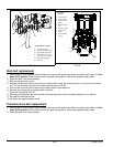
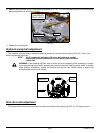
10.With the engine off, move the RH steering control lever into the neutral position and pull the lever all the way back
to the rear of the tractor as if you were going full speed in reverse. Now, slowly bring the lever back to the neutral
position and lock it into the brake position. This sets the steering damper in the correct neutral position. Tighten
the ball stud at the rear of the damper that is attached to the frame side panel on the RH side (FIG. 38). Once this
FIG. 35 FIG. 36
FIG. 37 FIG. 38
CONTROL LEVER IN THE
JAM NUT
STEERING
JAM NUT
NEUTRAL POSITION
CONTROL ROD
DAMPER
CONTROL LEVERS IN PARK BRAKE POSITION
fst2007jackstands.tif
ENGINE
JACK STANDS
GUARD
REAR DAMPENER
STEERING
DAMPENER
BALL STUD
spt2009_damper1.jpg


