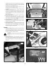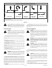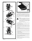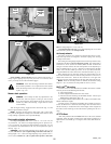
IMPORTANT: When access is required under the seat platform and
the seat is equipped with the optional arm rests, make certain to place
the control arms in the park brake position and pivot the arm rests
upward before placing the seat platform in the full forward position to
prevent arm rest damage.
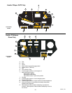
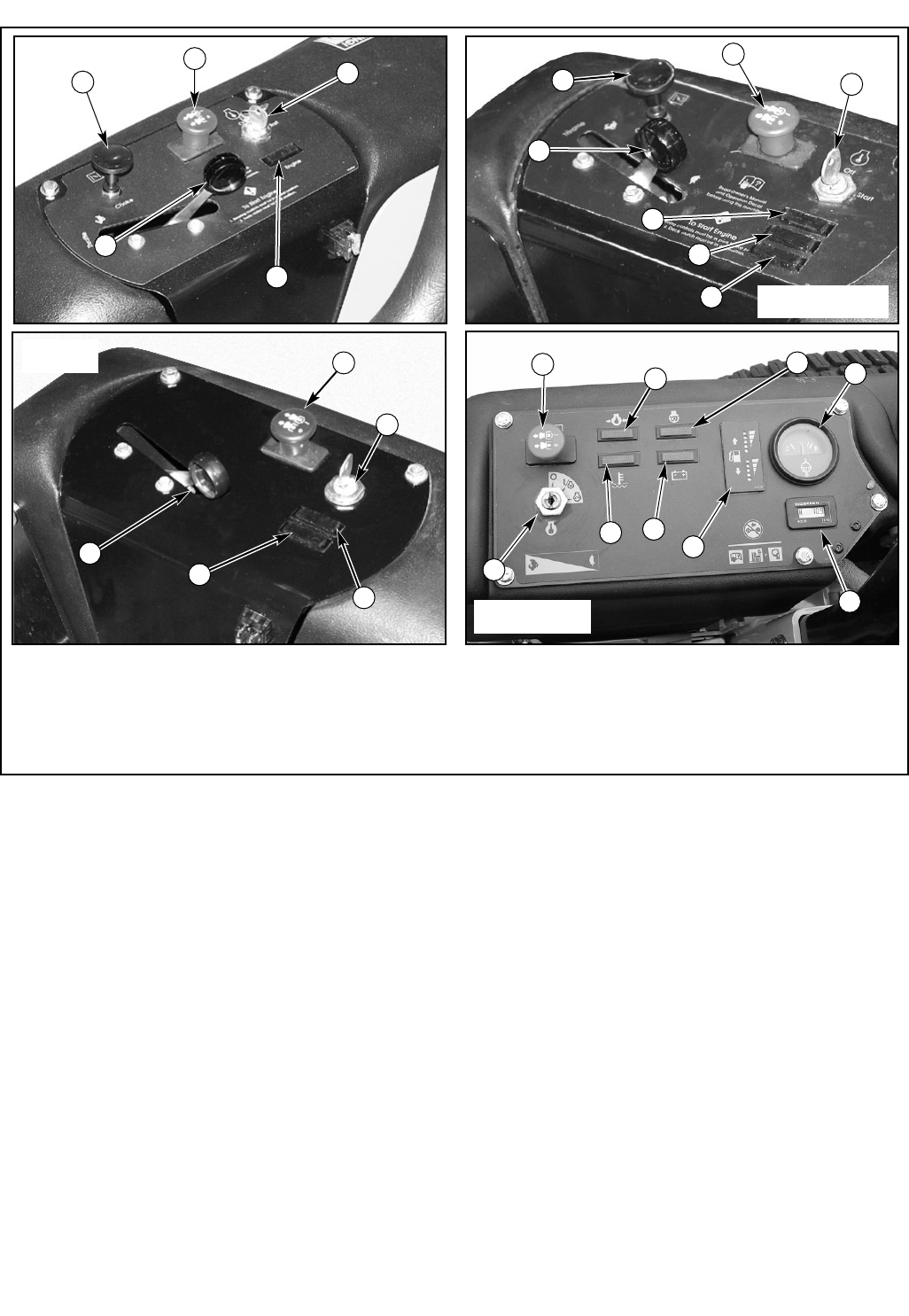
Control Panel
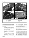
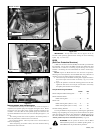
A. Choke control (Fig. 3-1) – a cable is linked to manually operate the
engine choke. When the lever is in the down position, the choke is
in the off (run) position. When the lever is pulled up, the choke is in
the on (start) position. Do not operate the machine in the on (start)
position. NOTE: The choke control is not used on Models 927053
& 927061 or any diesel powered models.
B. Throttle control (Fig. 3-1 & 3-2) — a cable is linked to engine
throttle for controlling engine speed. Move lever forward to
increase engine rpm, move lever rearward to decrease engine rpm.
C. Deck clutch switch (Fig. 3-1) — this switch engages the deck. Pull
the switch up to engage and push switch down to disengage the
clutch.
IMPORTANT: Never engage clutch with engine running at high
rpm or when the deck is under load. Clutch, belts or deck could be
damaged.
D. Ignition switch (Fig. 3-1) – a three position switch: “OFF”,
“RUN”, and “START”. With key inserted, rotate it clockwise to
“START” position; release key when engine starts, and switch will
automatically return to the RUN position.
Kohler EFI
units only
Kawasaki liquid
cooled units only
A
Figure 3-1
B
A
B
B
C
C
C
D
D
D
E
E
E
E
F
G
I
K
Control Panels
Shibaura diesel
units only
Hustler Z Shibaura Diesel units only — a three position switch:
“OFF”, “PRE-HEAT/RUN”, and “START”. With key inserted,
rotate it clockwise to the “PRE-HEAT/RUN” position. After pre-
heat has occurred (see “Diesel engine starting”, page 13) rotate the
key to the “START position; release key when engine starts, and
switch will automatically return to the “RUN” position.
E. Oil pressure light and alarm (Fig. 3-1) — this light comes on
when the ignition switch is placed in the RUN position and stays lit
until the engine is running and a safe oil pressure is developed. If
light comes on during operation, shut engine off immediately and
locate and correct the problem.
Models 927558 and 927566 only — an audible alarm will sound
when the engine oil pressure drops below normal operating pressure.
F. Check engine light (Fig. 3-1) — refer to Kohler engine owner’s
manual for details.
G. Temperature warning light and alarm (Fig. 3-1) — this light will
come on when the engine coolant temperature reaches an unsafe
level during operation. If light comes on, shut down the machine as
soon as possible. Never risk continued operation when light remains
on; high temperatures can severely damage the engine.
Never risk continued operation when light remains on: high
temperatures can severely damage the engine.
Models 927558 and 927566 only — an audible alarm will sound
when the engine coolant is close to overheating.
H. Temperature gauge and alarm (Fig. 3-1) — Hustler Z Shibaura
Diesel units only — this gauge reflects the engine coolant
601656_1108
15
A - Choke G - Temperature warning light
B - Throttle H - Temperature gauge
C - Deck clutch switch I - Alternator warning light
D - Ignition switch J - Hour meter
E - Oil pressure light K Glo-plug light
F - Check engine light L Fuel gauge
L
H
D
G
I
C
J


