


3-2 111782_0910
Mower deck preparation
1. Park the tractor on a flat surface and place the park brake
lever in the brake engaged position, place the PTO lever
in the “OFF” position and lower the attachment. Shut off
the ignition switch and remove the key from the switch.
Disconnect the negative battery cable.
2. Remove the right side pulley cover, discharge chute and
discharge chute bracket.
NOTE: Retain these parts as they will be re-installed
when the catcher is removed.
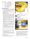
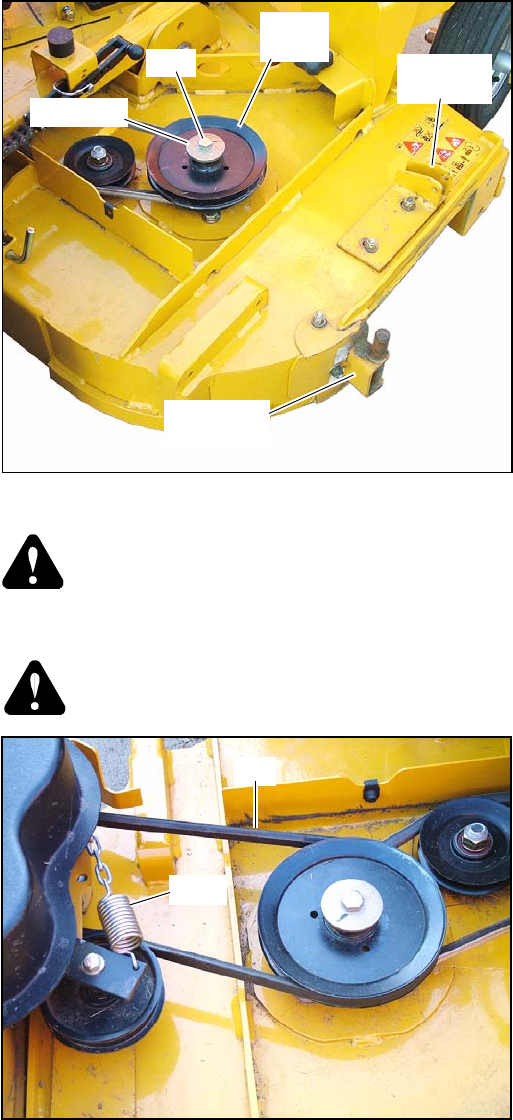
3. Release the deck belt tension. Remove the existing
spindle bolt and pulley from the right side blade spindle.
Replace the pulley with the double pulley and place the
existing cup washer between the head of the new bolt and
the drive pulley. Torque the bolt into the pulley before
threading the bolt into the spindle shaft. Torque top
spindle bolt to 118 ft.-lbs. Thread the pulley, cup washer
and bolt assembly into the right hand spindle shaft.
Torque bolt to 118 ft.-lbs. Figure 3-1
NOTE: There are two double pulleys shipped with this
catcher. Two different deck gearboxes have been used on
these decks.
Decks built prior to serial number 09080000 – The
gearbox is painted black and the pulley is held onto the
drive shaft with set screws. Use pulley, 602244, on these
decks.
Decks built with serial number 09080000 and later –
The gearbox on these decks is painted gray. The pulley is
held onto the drive shaft with a cap screw. Use pulley,
524785, on these decks.
CE Decks regardless of serial number – The gearbox is
painted black and the pulley is held onto the drive shaft
with set screws. Use pulley, 602244, on these decks.
4. Attach the blower mount to the top of the deck. Figure 3-
1
5. Attach the blower assembly to the deck mount. Figure 3-
1
6. Re-adjust the blower pivot mount, if necessary, to
minimize the gap between the deck opening and blower
housing. Tighten all hardware.
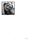
7. Install and route the blower belt to the deck. Tension the
belt using the chain and spring. Pull the chain until the
spring extension is 6” hook to hook. Figure 3-2 & Figure
3-3
8. Re-tension the deck drive belt.
9. Attach the pulley cover.
10. Swing the housing so that it is tight against the deck and
insert the clevis pin and hair pin thru the latch..
WARNING: Do not operate deck without discharge
chute or complete catcher system in place.
Tractor Preparation
WARNING: Allow engine and muffler to cool before
assembling the unit to the tractor.
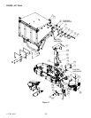
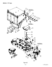
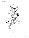
1. Position the rear support frame and the weights (centered
side to side) to the rear of the tractor. Make sure the upper
holes in the rear support frame are positioned as shown.
Attach with the hardware shown. Figure 3-10
NOTE: It is recommended that 3 people assist when
attaching the box assembly to the rear support frame.
2. Locate the box assembly onto the rear support frame and
attach to the rear support frame with the hardware shown.
Figure 3-10
35 056077 CS .250-20 X 1.00 HX G5 ZN 1
36 068551 NT .250-20 HX NL ZN 1
37 768523 FW .343X.687X.051/080 HD ZN/YL 8
38 064014 CS .312-18 X .875 HS G5 ZN 2
39 064006 CS .312-18 X .625 HX G5 ZN 4
40 058776 NT .312-18 HX NL ZN 2
41 760306 FLEXIBLE TRANSFER TUBE 1
42 022608 HOSE CLAMP 2
43 544501 BLOWER ASSEMBLY 1
INDEX NO. PART NO. DESCRIPTION QTY.
Figure 3-1
Figure 3-2
Cup washer
Bolt
Blower pivot
mount
Chute
mount w/a
Double
pulley
Spring
Belt