


7
ASSEMBLY
NOTE: You may now roll or drive your tractor off the skid.
Follow the ap pro pri ate instruction below to remove the
tractor from the skid.
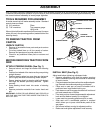
TO ROLL TRACTOR OFF SKID (See Op-
er a tion section for location and function of
con trols)
• Press lift lever plunger and raise attachment lift lever
to its highest po si tion.
• Release parking brake by de press ing clutch/brake
ped al.
• Place freewheel control in "trans mis sion dis en gaged
position" (See “TO TRANS PORT” in the Op er a tion
section of this manual).
• Roll tractor forward off skid.
FIG. 2
FIG. 3
02466
02464
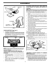
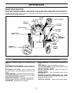
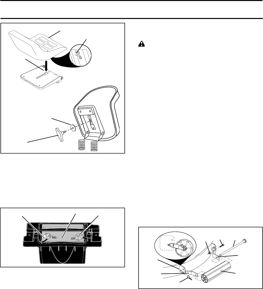
SEAT PAN
SHOULDER
BOLT
ADJUSTMENT
KNOB
FLAT WASHER
SEAT
TO DRIVE TRAC TOR OFF SKID (See Op-
er a tion section for location and function of
con trols)
WARNING: Before start ing, read, un der stand and fol low
all in struc tions in the Op er a tion section of this man u al. Be
sure tractor is in a well-ventilated area. Be sure the area in
front of tractor is clear of other peo ple and objects.
• Be sure all the above assembly steps have been com-
pleted.
• Check engine oil level and fi ll fuel tank with gasoline.
• Place freewheel control in "trans mis sion en gaged"
po si tion (see "TO TRANSPORT" in Op er a tion section
of this manual).
• Sit on seat in operating position, depress clutch/brake
pedal and set the parking brake.
• Place motion control lever in neutral (N) position.
• Press lift lever plunger and raise attachment lift lever
to its highest position.
• Start the engine. After engine has started, move throttle
control to idle position.
• Release parking brake.
• Slowly move the mo tion control lever for ward and slowly
drive tractor off skid.
• Apply brake to stop trac tor, set park ing brake and place
motion con trol lever in neutral po si tion.
• Turn ignition key to "STOP" position.
Continue with the in struc tions that follow.
02746
CHECK BATTERY (See Fig. 3)
• Lift hood to raised position.
• If this battery is put into service after month and year
indicated on label (label located between terminals)
charge battery for minimum of one hour at 6-10 amps.
(See "BATTERY" in the Maintenance section of this
manual for charg ing in struc tions).
LABEL
TERMINAL TERMINAL
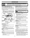
FIG. 4
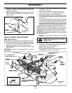
TO ATTACH NOSE ROLLER (See Fig. 4)
• Assemble brackets "A" and "B" to the inside of mower
mounting brack ets as shown. Tighten securely.
NOTE: Be sure bracket tabs are po si tioned in tab holes
in mower brackets.
• Position nose roller between brackets and install rod
and retainer spring.
02612
NOSE
ROLLER
HEX
BOLT
"A"
BRACKET
"B"
BRACKET
LOCK
NUT
TAB
HOLE
RETAINER SPRING
ROD
ASSEMBLE GAUGE WHEELS TO MOWER
DECK (See Fig. 5)
The gauge wheels are designed to keep the mower deck in
proper position when operating mower. Be sure they are prop-
erly adjusted to ensure optimum mower performance.
• Slide gauge wheel bar down into bracket channel, Be sure
that gauge wheel bar aligning holes are on top. As sem ble
gauge wheels as shown using shoulder bolts, 3/8 wash-
ers and 3/8-16 center locknuts and tighten securely.