


6
ASSEMBLY
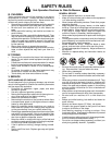
FIG. 2
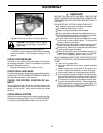
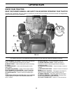
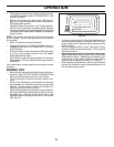
ADJUST SEAT (See Fig. 2)
• Sit in seat.
• Lift up adjustment lever (A) and slide seat until a com-
fortable position is reached which allows you to press
clutch/brake pedal all the way down.
• Release lever to lock seat in position.
NOTE: You may now roll or drive your tractor off the skid.
Follow the ap pro pri ate instruction below to remove the
tractor from the skid.
WARNING: Before start ing, read, un der stand and fol low
all in struc tions in the Op er a tion section of this man u al. Be
sure tractor is in a well-ventilated area. Be sure the area in
front of tractor is clear of other peo ple and objects.
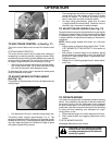
TO ROLL TRACTOR OFF SKID (See Op-
er a tion section for location and function of
con trols)
• Raise attachment lift lever to its highest po si tion.
• Release parking brake by de press ing brake ped al.
• Place freewheel control in dis en gaged po si tion to dis-
en gage trans mis sion (See “TO TRANS PORT” in the
Op er a tion section of this manual).
• Roll tractor forward off skid.
TO DRIVE TRAC TOR OFF SKID (See Op-
er a tion section for location and function of
con trols)
• Be sure all the above assembly steps have been com-
pleted.
• Check engine oil level and fill fuel tank with gasoline.
• Place freewheel control in "trans mis sion engaged"
position (see "TO TRANSPORT" in Operation section
of this manual).
• Sit on seat in operating position, depress brake pedal
and set the parking brake.
• Raise attachment lift lever to its highest position.
• Remove key from bag and start the engine (see "TO
START" in the Operation section of this manual). After
engine has started, move throttle control to idle (slow)
position.
• Release parking brake.
A
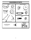
Your new tractor has been assembled at the factory with exception of those parts left unassembled for shipping pur-
poses.
TOOLS REQUIRED FOR ASSEMBLY
A socket wrench set will make assembly easier. Stan dard
wrench sizes are listed.
(1) 3/4" wrench (1) Utility knife
(1) 9/16" wrench (1) Pliers
(2) 7/16" wrenches (1) Tire Pressure Gauge
When right or left hand is mentioned in this man ual, it
means from your point of view, when you are in the operat-
ing po si tion (seated be hind the steer ing wheel).
TO REMOVE TRACTOR FROM
CARTON
UNPACK CARTON
• Remove all accessible loose parts and parts cartons
from carton .
• Cut along dashed lines on all four panels of carton.
Remove end panels and lay side panels flat.
• Remove mower and packing materials.
• Check for any additional loose parts or cartons and
remove.
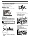
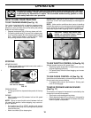
CONNECT BATTERY (See Figs. 1)
CAUTION: Do not short battery ter-
minals by allowing a wrench or any
other object to contact both terminals
at the same time. Before connect-
ing battery, remove metal bracelets,
wristwatch bands, rings, etc.
Positive terminal must be connected
first to prevent sparking from acci-
dental ground ing.
• Lift hood to raised position.
• Remove terminal protective caps and discard.
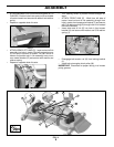
• If this battery is put into service after month and year
indicated on label (L) (label located between terminals)
charge battery for minimum of one hour at 6-10 amps.
(See "BATTERY" in the Maintenance section of this
manual for charg ing in struc tions).
• First connect RED battery cable to positive (+) terminal
with hex bolt and keps nut as shown. Tighten securely.
Slide terminal cover over terminal.
• Connect BLACK grounding cable to negative (-) ter-
minal with remaining hex bolt and keps nut. Tighten
securely.
FIG. 1
02954
L