


6
ASSEMBLY
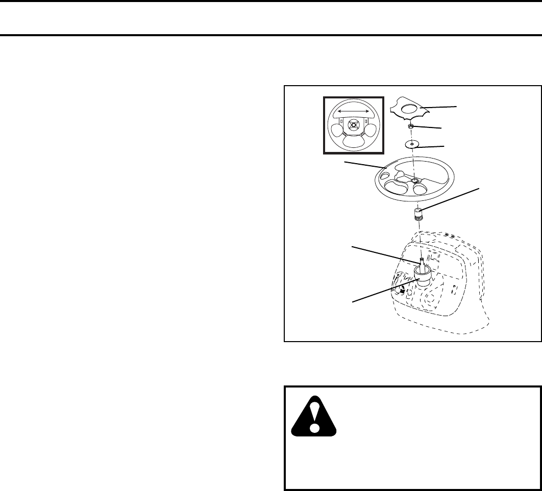
FIG. 1
Your new tractor has been assembled at the factory with exception of those parts left unassembled for shipping pur-
poses. To ensure safe and proper operation of your tractor all parts and hardware you assemble must be tightened
securely. Use the correct tools as necessary to insure proper tightness.
TOOLS REQUIRED FOR ASSEMBLY
A socket wrench set will make assembly easier. Stan dard
wrench sizes are listed.
(2) 9/16" wrench Utility knife
(1) 1/2" wrench Tire pressure gauge
(1) 3/4" wrench Pliers
(1) 3/4" socket with drive ratchet
When right or left hand is mentioned in this man ual, it means
when you are in the operating po si tion (seated be hind the
steer ing wheel).
TO REMOVE TRACTOR FROM
CARTON
UNPACK CARTON
• Remove all accessible loose parts and parts cartons
from carton .
• Cut along dotted lines on all four panels of carton.
Remove end panels and lay side panels fl at.
• Remove mower and packing materials.
• Check for any additional loose parts or cartons and
remove.
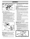
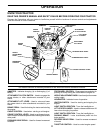
CONNECT BATTERY (See Fig. 2)
CAUTION: Do not short battery ter-
minals by allowing a wrench or any
other object to contact both terminals
at the same time. Before connect-
ing battery, remove metal brace-
lets, wristwatch bands, rings, etc.
Positive terminal must be connected
fi rst to prevent sparking from accidental
ground ing.
• Lift hood to raised position.
• Open terminal access doors, remove terminal protec-
tive caps and discard.
• If this battery is put into service after month and year
indicated on label (label located between terminals)
charge battery for minimum of one hour at 6-10
amps.
• First connect RED battery cable to positive (+) battery
ter mi nal with hex bolt and keps nut as shown. Tighten
securely.
• Connect BLACK grounding cable to negative (-) battery
terminal with remaining hex bolt and keps nut. Tighten
securely.
• Close terminal access doors.
Use terminal access doors for:
• Inspection for secure connections (to tighten har
dware).
• Inspection for corrosion.
• Testing battery.
• Jumping (if required).
• Periodic charging.
BEFORE REMOVING TRAC TOR FROM
SKID
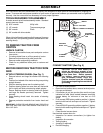
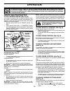
ATTACH STEERING WHEEL (See Fig. 1)
• Remove locknut and large fl at wash er from steering
shaft.
• Position front wheels of the tractor so they are pointing
straight forward.
• Slide the steering sleeve over the steering shaft.
• Position steering wheel so cross bars are horizontal
(left to right) and slide onto steering wheel adapter.
• Secure steering wheel to steering shaft with locknut
and large fl at wash er pre vi ous ly removed. Tight en
securely.
• Snap steering wheel insert into cen ter of steering
wheel.
• Remove protective materials from tractor hood and
grill.
IMPORTANT: CHECK FOR AND REMOVE ANY STAPLES IN
SKID THAT MAY PUNCTURE TIRES WHERE TRACTOR IS TO
ROLL OFF SKID.
0
2
8
1
8
STEERING WHEEL
INSERT
LOCK NUT
LARGE FLAT WASHER
STEERING
WHEEL
STEERING
SHAFT
STEERING
SLEEVE
STEERING
WHEEL ADAP-
TOR