


19
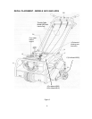
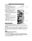
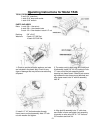
TINE AND TINE SHAFT
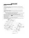
Tine Replacement
1. Turn off engine and remove weights.
2. Fold handle on the AR19 Model.
3. Note direction of tine bolt.
4. Remove and replace tines by loosening stop bolt. Remove retaining bolt and old tine, insert new
tine and fasten with retaining bolt in the same direction as it was removed. When all tines are
replaced, tighten stop bolts. NOTE: Replace worn lock nuts to insure that bolts will hold tines in
place.
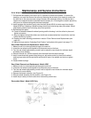
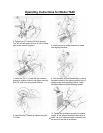
Tine Shaft Bearing Removal and Replacement
1. Turn off engine and remove weights.
2. Remove drive guard cover.
3. Fold handle for better access to tines (on Model AR19 only).
4. Elevate approximately 4", block and chock rear wheels.
5. Manually cycle the drive chain for acess to master link.
6. Turn chain idler adjustment bolt counter clockwise to loosen the chain.
7. Remove the master link and free rotor sprocket.
8. Remove the tine rotor shaft bearing bolts (4).
9. Remove the rotor shaft assembly.
10. Remove outer rotor bearing by loosening the set screw in the collar.
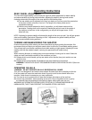
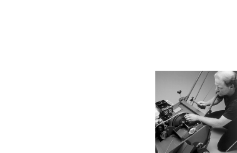
11. Unlock collar (best accomplished by using a hammer and pin punch). Insert pin punch into the
hole next to the set screw and, using the hammer, with moderate striking, hit collar so that it
rotates in the opposite direction the rotor would normally turn.(see Figure 19)
12. Reverse these steps to reinstall.
13. Refer to sections “Chain Removal and Replacement” and “Adjusting Chain Tension” for chain
replacement and adjustment of chain tension. (see page 16).
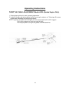
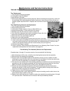
Free-Wheeling Tine Assembly Removal and Replacement
Complete steps 1 through 12 in previous section, then proceed with the following:
1. After the bearing is off the rotor, unlock the inner bearing that secures the tine assembly.
2. Remove outer free-wheeling tine assembly.
3. Place the new rotor assembly beside the old assembly so that you have a pattern to follow
indicating the correct direction which the new tines are to be installed. You can also refer to the
tines on the fixed tine assembly as an example of proper assembly.
4. Once the tines are installed on the free-wheeling assembly, re-install the inner and outer bearing
assemblies on the free-wheeling assembly with the bearing hubs facing toward the fixed tines.
Make sure that the inner bearing has a locking collar. Hand tighten the nuts only.
5. Slide the new free-wheeling tine assembly on the shaft making sure that the tine direction
matches the direction of the fixed tine assembly. The bearing with the locking collar faces the
fixed tines and butts up against the shoulder of the shaft.
6. Tighten the four nuts on the bearing assemblies.
7. Lock the bearing collar in place with the hammer and punch making sure the collar locks in the
same direction as the rotation of the rotor.
8. Replace outer shaft bearing and re-install the entire rotor assembly by reversing steps 1 through
12 in previous action. Instructions are for one side. Both are procedurally identical.
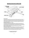
Figure 19
Maintenance and Service Instructions